Low-alloy steel is highly sensitive to corrosion. For this reason parts and structures made of this material are often protected by a zinc (Zn) coating. Zinc coating inhibits corrosion but has the disadvantage that as soon as it is damaged – even in a small area only– corrosion sets in even more severe compared to an unprotected part. This effect can be avoided by substituting the Zn coating bya ZnAl coating, additionally containing aluminum (Al).
This article describes the examination of low-alloy steel parts coated with Zn an with ZnAl and subjected to corrosion treatment after damaging the protective layer using (micro X-ray fluorescence) Micro-XRF. The distribution analysis of the involved elements contributes to an improved understanding of corrosion processes and the influence of Al on the reduction of corrosion.
Instrumentation
The analysis was performed with the Bruker M4 TORNADO 2D Micro-XRF spectrometer. This instrument features:
- Large vacuum chamber for sample sizes of up to200 x 300 x 125 mm³
- Fast X-Y-Z TurboSpeed stage for distribution analysis“on the fly”
- Effective excitation of fluorescence using a high brillianceX-ray tube combined with X-ray optics for concentration of tube radiation to spot sizes below 25 µm
- A silicon driftdetector (SDD) for X-ray detection with highest count rate capability
The samples
The samples were pieces of low-alloy steel which were treated differently. Parts were either coated with galvanic Zn layers or dip-coated in a ZnAl alloy melt at approx. 600 °C.
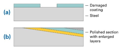
Figure 1. (a) Layer structure of steel sample with coating and damaged area, (b) structure of prepared sample (polished section)
The coating was removed at a small area of the sample (as shown in Fig. 1a). The samples were subsequently corroded in seawater at 50° C for 64 hours. For distribution analysis the samples were embedded in epoxy. Because coatings and corrosion layers are relatively thin, the samples were polished at an angle of 5.7 deg. This led to an artificial enlargement of the layers by a factor of 10. The according structure is shown in Fig. 1b. A sample prepared in this manner is shown in Fig. 2. Note the strong corrosion effects in the center of the part, this is the area where the protective coating was removed.
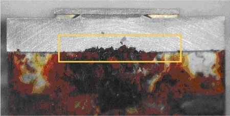
Figure 2. Sample as prepared for analysis, yellow rectangle indicates the area of analysis
Analyses
The analyses of differently treated samples were performed by element mapping with the following parameters:
- Mapped area: approx. 20 x 5 mm²
- Step size: 20 µm
- Measurement time: 10 ms/per pixel, less than 1 h total
The multi-element distributions of Zn and ZnAl coated samples are depicted in Fig. 3 andFig. 4. Both figures show Zn-coated areas (green) on the left and right side and an area with removed Zn coating in the middle. The red areas in the upper section of both figures display the polished base material (Fe). Cl (blue) and S (purple) inthe lower section result from the epoxy as it contains Cl and S, which cover part of the polished sample. The elements can also be found also within the cracks in the corrosion layer. They are residue from the seawater treatment. The distribution of Al in Fig. 4 is light blue. It is concentrated within the coated area between steel (Fe) and Zn coating.
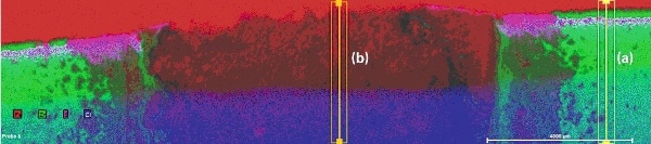
Figure 3. Multi-element distribution of Zn-coated steel after seawater treatment, with areas of line scans
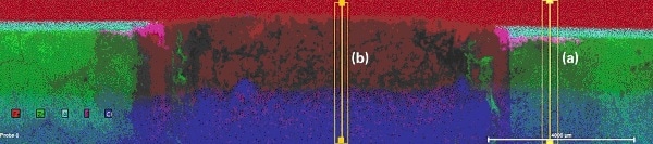
Figure 4. Multi-element distribution of ZnAl-coated steel after seawater treatment, with areas of line scans
Comparing the boundaries of the element distributions in Fig. 3 and Fig. 4 it can be concluded that conventional Zn coating is more sensitive to corrosion than ZnAl coating.The aluminum from the ZnAl coating obviously forms a layer directly on the surface of the steel part.
More detailed information can be taken from the line scans perpendicular to the layer system (yellow rectangles in Figs. 3 and 4, representing lines broadened for improvement of measurement statistics). These line scanscould be calculated from map data because complete spectra were saved for all pixels. For a better understanding of the differences in corrosion protection the line scans were extracted for two different areas of each sample one at an area with intact coating (line scans (a)) and a second in the area where the coating was removed (line scans (b)). Also element concentrations were normalized to the highest concentration of every element along the line to “100”. The purpose of this procedure is to fit elements of high concentration (Fe, Zn) in the same Y axis range as those with low concentrations (Al, S, Cl). The advantage of this procedure is that changes in the concentration of all elements can be spotted easily (which is the purpose of this investigation). Disadvantages are that the lines and scaling do not reflect absolute concentrations of the elements and that statistical noise is well visible in the lines of the minor elements. The results are shown in Fig. 5a to 6b.
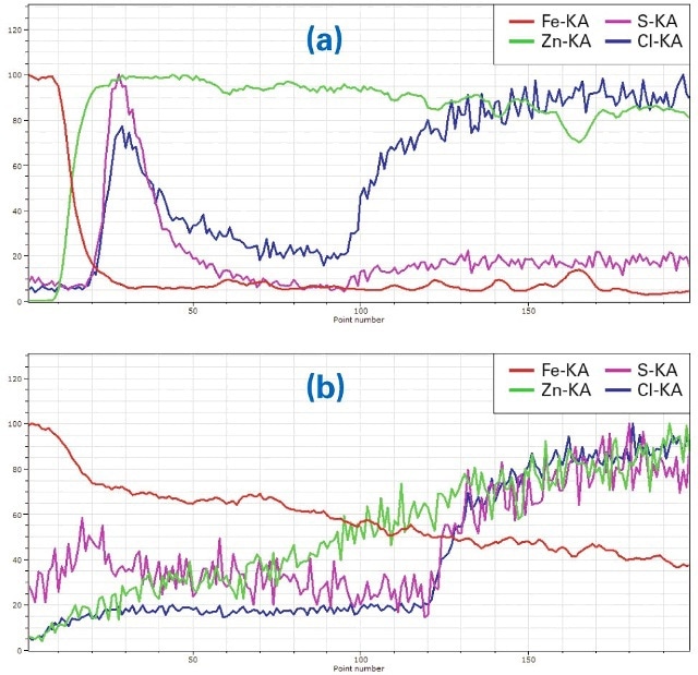
Figure 5. (a) Line scan ((a) in Fig. 3) of Zn-coated material, (b): Line scan ((b) in Fig. 3), in the region where Zn was removed and the material corroded
Fig. 5a shows the linear element distribution of the line scan (a) in Fig. 3 perpendicular through the layer system in the Zn-coated area. At the top of the sample, respectivelyon the left side of the line scan, the Fe intensity (red) is high as it is from the base material. It decreases significantly while the Zn intensity of the coating (green) increases. The higher intensities of S (purple) and Cl (blue) on the left are an effect of corrosion penetration to the sides, also visible as purplish areas to the left and right of the main corroded zone. Cl increases on the right side of the line due to its content in the epoxy. The sharp boundary between Fe and Zn shows that the corrosion protection is intact.
Fig. 5b shows the element distribution of the line scan b in Fig. 3 in the area of the same sample, where Zn was removed. Here the distribution of Fe decreases slowly because it is diffused into the corroded region by the corrosion process. Zn increases slowly due to the same process. Both Cl and S increase again on the right side of the line scan – a result of their content in the epoxy. In general itcan be seen that the corrosion protection is less effective because Fe is diffused in the corrosion area.
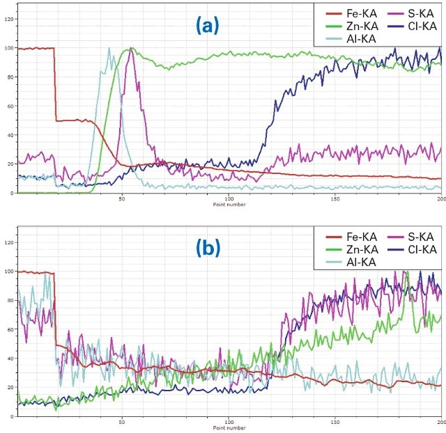
Figure 6. (a) Line scan ((a) in Fig. 4) of ZnAl-coated material, (b) Line scan (b in Fig. 4), in the region where the coating was removed
The element distributions in Fig. 6a and Fig. 6b show the distributions of a sample after the same seawater treatment but with ZnAl coating. The decrease of Fe in the coated area (Fig. 6a, line scan a in Fig. 4) is very strong. Al is mainly concentrated on top of the steel and the Zn coating is almost free of Al. S again penetrates between steel and protective coating but is blocked from reaching the steel by the Al layer (also compare figures 3 and 4). On the right side both S and Cl increase as a result of the epoxy embedding.
Also in the area free from Zn (Fig. 6 (b, line scan b in Fig. 4)the Fe intensity decreases significantly but the Al intensityis very low. The concentrations of Cl and Zn are also low in that area. They increase as well as S in the epoxy.
Conclusion
Micro-XRF distribution analysis of theses samples with the M4 TORNADO provides rich results in a short time. All layers can be made visible and the corrosion process studied in depth, enhanced with the help of sample preparation (embedding and grinding at an angle).
From investigations presented here, it can be concluded that even in case of an intact protection layer corrosion protection with a ZnAl alloy is more efficient than a Zn only coating. Because Al is concentrated in a layer directly on the steel surface it provides additional protection. Additionally, Al could be seen to reduce corrosion even in caseof a damaged protection layer.

This information has been sourced, reviewed and adapted from materials provided by Bruker Nano Analytics.
For more information on this source, please visit Bruker Nano Analytics.