Plotting three Euler angles using an RGB color scheme is the best way of generating an orientation map, which is normally referred to as a Euler map (Figure 1).
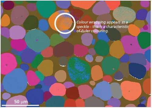
Figure 1. Euler angle coloring orientation map for the sample of tungsten hardened alloy. The color wrapping is characteristic of Euler coloring
The sample orientation relative to a crystal, where each crystal structure has a specific reference orientation, is best described with Euler angles.
The coordinate systems are rotated about various different axes till they coincide with each other. Figure 2 shows the most common way to use the Bunge notation where the three Euler angles characterize the following rotations:
- Rotation of Φ1 about the z-axis followed by,
- Rotation of Φ about the rotated x-axis followed by,
- Rotation of Φ2 about the rotated z-axis
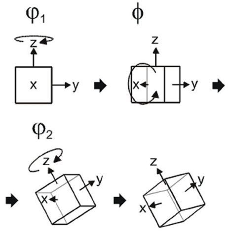
Figure 2. Euler angles and rotations
Euler Colored Maps
The Euler colored maps provide a basic presentation of the microstructure. There are however limitations of the Euler maps. One drawback is that small orientation changes do not correspond to small variations in the color scale causing confusion while seeing an Euler map.
In order to overcome these drawbacks, a different map display is used. A different color scheme is used by the Inverse Pole Figure (IPF) color scheme, which can be interpreted easily and does not have considerable color changes with small orientation changes.
Each of the corners of the inverse pole figure (Figure 3) are assigned with a color to form the color scheme. For each map, a reference sample direction is selected and the color assignment is done based on determined crystal orientation and selected viewing direction.
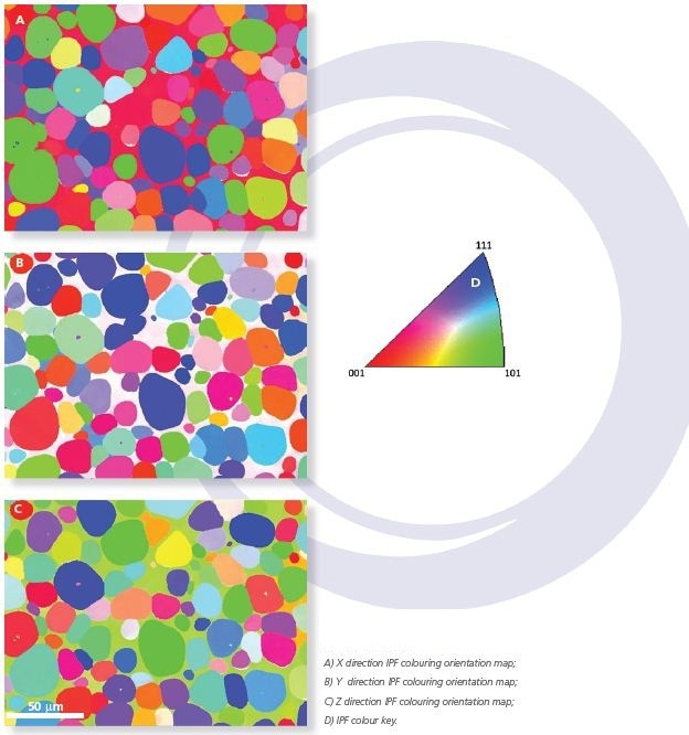
Figure 3. Crystal orientation maps obtained for a sample of tungsten hardened alloy collected at 20 kV accelerating voltage. A) X direction IPF colouring orientation map; B) Y direction IPF colouring orientation map; C) Z direction IPF colouring orientation map;D) IPF colour key
Misorientations
When compared to other microstructural characterization techniques, EBSD has a considerable advantage as it can determine the misorientation between two crystals. A triclinic crystal, which has no symmetry, is ideal for defining a misorientation. The unique rotation axis and the rotation angle that maps one crystal lattice onto other, for any two triclinic crystals is termed as the misorientation axis and misorientation angle respectively.
Grains and Grain Boundaries
A grain may be defined as a 3D crystalline volume in a sample differing from its surroundings in crystallographic orientation but has minimal variation internally. In order to determine the grains in a dataset, it is necessary to define a critical misorientation angle where all boundary segments with an angle more than the defined critical angle are to be considered grain boundaries.
By determining the misorientation between all pixel pairs, one can identify the boundaries encompassing the separate grains. By using this data together with the phase information, the grain size distribution can be determined from different phases in the sample.
Similarly, generating a map showing the spatial distribution of the grain boundaries offers further information about the microstructure. Typically, a map can be generated showing low-angle boundaries providing information on the sub-structure of individual grains (Figure 4).
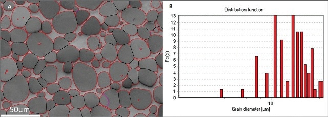
Figure 4. Grain boundary data for a sample of tungsten hardened alloy A) Grain boundary positions superimposed on the pattern quality Image with grain boundaries higher than 2 degrees highlighted In purple, higher than 10 degrees in black, and phase boundaries are in red; B) Histogram of grain sizes from the Tungsten (W) phase. The average grain size is shown to be 17µm.
The misorientation axis can also be determined while calculating the misorientation angle. This implies that EBSD data can be used to determine specific boundaries defined not just by a misorientation angle but by misorientation angle and misorientation axis combined.
Twin boundaries, a subset of coincident site lattice (CSL) boundaries are a very common example. CSLs are characterized by S, where S is the ratio of the CSL unit cell compared to the standard unit cell. Two CSL relationship examples are shown in Fig. 5.
![A) The sigma 3 boundary (twin boundary) is a 60° rotation about the [111] direction. B) The sigma 5 boundary is a 36.9° rotation about the [100] direction.](https://d12oja0ew7x0i8.cloudfront.net/images/Article_Images/ImageForArticle_11775_44827078355451392583.jpg)
Figure 5. A) The sigma 3 boundary (twin boundary) is a 60° rotation about the [111] direction. B) The sigma 5 boundary is a 36.9° rotation about the [100] direction.
In most materials, grains do not feature a random orientation distribution and in such cases, the sample is considered to have a preferred texture or orientation. Based on the orientation data obtained from various points in each phase, it is possible to check if a particular phase has a preferred orientation.
This can be done in a number of ways, one way being looking at maps featuring the points with an orientation close to a specified reference orientation, referred to as texture maps. As they contain information about the spatial distribution of the reference texture, they can be very useful.
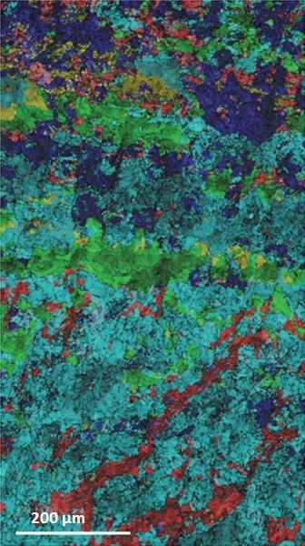
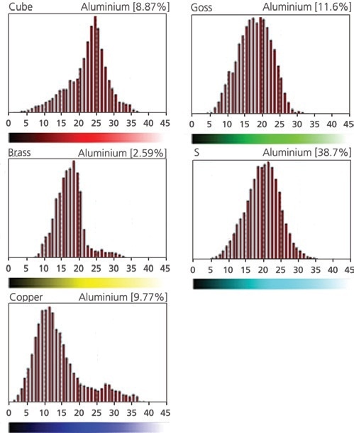
Figure 6. Area fractions for multiple reference textures for a sample of cold rolled Al Mg alloy.
Also, pole figures can be generated for identified phases. Pole figures are very useful in determining relationships between the orientations near the interface boundaries (Figure 7).
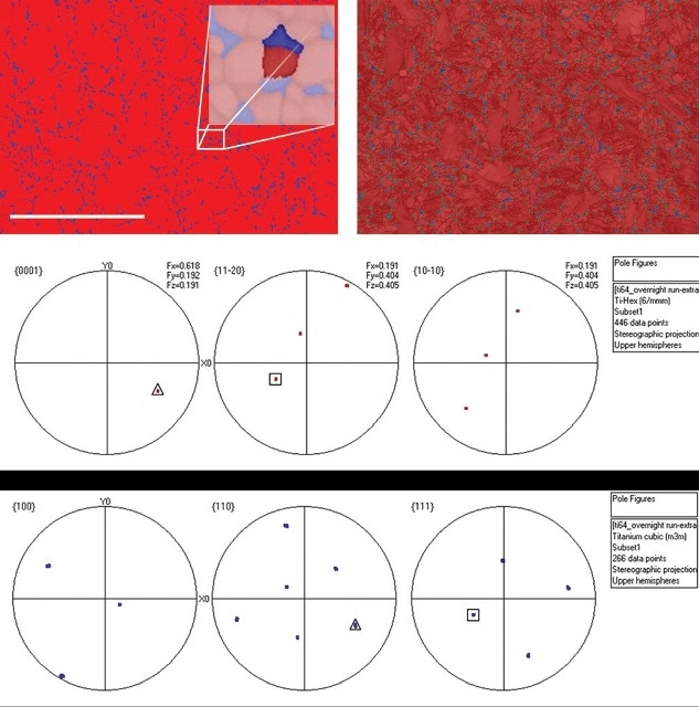
Figure 7. Orientation relationship between Ti alpha and Ti beta A) Phase map of Ti 64 shows the phase distribution and one grain from each phase selected for further analysis; Ti alpha is red and Ti beta blue.B) Pole figures from the selected Ti alpha grain.C) Pole figures from the selected Ti beta grain.D) Phase map plus band contrast and grain boundaries with Burgers orientation relationship {0001}//{011} and <2-1-10>//< 11-1> in green.
Pole Figures
Pole figures are used to plot 3D orientation information in two dimensions such as on a paper sheet or a computer screen. They are suited for showing the orientations of specific crystallographic planes and directions within a sample (i.e. for plotting the texture) and, as such, are invaluable for EBSD.
The projected position of a specific set of crystallographic planes, wherein the normals or poles have been projected to a sphere and then to a circle, is shown in a pole figure. The two techniques for doing this are the equal area projection and the stereographic projection.
Beginning at a single crystal, shown by the unit cell on the left in Figure 8, it is oriented in a specific pattern relative to the sample shown at the bottom left of Figure 8.
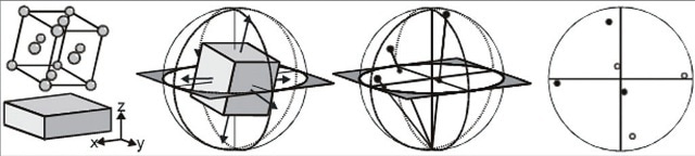
Figure 8. The production of a stereographic projection for a single crystal (in this case a unit cell), which is orientated in a particular manner to the sample.
As shown in the second drawing, the {100} plane normals, of which there are 6 for this cubic crystal, would project onto a sphere. A plane passing through the sphere center and parallel to the sample surface will intersect the sphere as a circle. The points where the {100} plane normals touch the sphere to the sphere's opposite pole are then joined.
This is shown in the third image. While observing the circle, it is seen that the 3D crystallographic directions have been converted into points. This is the {100} pole figure. It is possible to repeat this with other grain orientations to provide a pole figure showing the distribution of that particular set of planes within the sample.
Inverse Pole Figures
Crystallographic directions in the sample coordinate system are plotted in a pole figure whereas sample directions in the crystallographic coordinate system are plotted in an inverse pole figure.
For instance, rather than plotting the <111> directions with respect to the rolling direction (RD) and normal direction (ND), an inverse pole figure can plot the rolling direction in terms of the major crystal directions (i.e. [100], [110] and [111]).
There are several advantages of inverse pole figures over conventional pole figures:
- In an inverse pole figure, each data point appears as a single point. For higher symmetry phases, in several pole figures, a single data point may be represented by multiple points on the pole figure.
- It is mostly easy to determine specific fiber textures with an inverse pole figure.
- Inverse pole figures are normally used as a default coloring scheme for orientation maps (by coloring the three corners of the inverse pole figure triangle with the primary colors).
The form of an inverse pole figure is based on the Laue group of the relevant phase. This determines the size of the “unit triangle” such as the symmetrically equivalent space in the whole stereographic projection.
For example, a triclinic crystal (Laue group 1) has no symmetry and hence the complete pole figure is required to show all the possible crystal directions. Hence for triclinic structures, the inverse pole figure is similar to a pole figure – a full circle.
With increase in structure symmetry, the size of the symmetrically equivalent region decreases until, for Laue group 11 (cubic high), there are 24 symmetrically equivalent regions in the full circle. This is seen in Figure 9, with the standard unit triangle highlighted in the IPF colorings scheme.
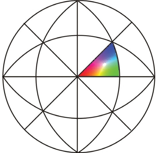
Figure 9. The 24 symmetrically equivalent regions in the (high) cubic inverse pole figure.

This information has been sourced, reviewed and adapted from materials provided by Oxford Instruments NanoAnalysis.
For more information on this source, please visit Oxford Instruments NanoAnalysis.