For a thermoset, the ion viscosity is the frequency independent resistivity (ρDC). In most cases, ion viscosity varies in proportion to mechanical viscosity prior to gelation, and to modulus after. This makes ion viscosity a useful measure of material state through the entire cure.
Dielectric Cure Curve
Figure 1 shows the typical ion viscosity behavior of a thermoset with one temperature ramp step and one temperature hold step.
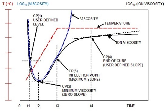
Figure 1. Typical ion viscosity behavior of a curing thermoset
The dielectric cure curve is characterized by four Critical Points (CP):
- CP(1)—A user defined level of ion viscosity, generally applied to determine the onset of material flow.
- CP(2)— Ion viscosity minimum, which closely corresponds to the mechanical viscosity minimum.
- CP(3)—Inflection point, when the reaction rate begins to slow, can be related to gelation but does not indicate gelation.
- CP(4)—A user defined slope to define the end of cure.
Dielectric/Conductivity Sensors
Dielectric instrumentation quantifies the resistance (R) and capacitance (C) between two electrodes at a specific frequency. It is possible to model the Material Under Test (MUT) between the two electrodes as a resistance in parallel with a capacitance (Figure 2).
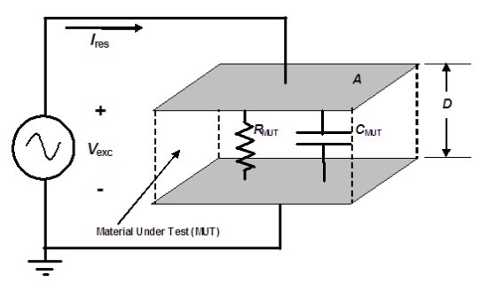
Figure 2. Electrical model of dielectric Material Under Test
Figure 3 shows simple parallel plate electrodes, which are capable of measuring the dielectric properties of material between them. The A/D ratio is a figure of merit, where ‘A’ is the electrode area and ‘D’ is the distance between them. A larger A/D ratio represents greater sensor sensitivity.
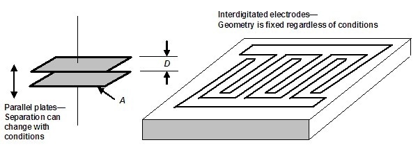
Figure 3. Comparison of parallel plate and interdigitated electrodes
The A/D ratio is also the scaling factor used to calculate permittivity from capacitance, and resistivity from resistance. However, the value D can vary with pressure or with material expansion and contraction, leading to erroneous results.
Interdigitated electrodes, shown in Figure 3, are the alternative solution, where the electrodes are supported by a rigid substrate, and therefore the planar structure remains unchanged with pressure or with MUT expansion and contraction. A bulk measurement is made by the parallel plate sensor, whereas a surface measurement is made by an interdigitated sensor.
As a rule of thumb, interdigitated electrodes with the same width and separation “see” into material to a depth roughly equal to the width of the electrode. The A/D ratio can also be applied to interdigitated electrodes as a figure of merit, and is the scaling factor to calculate resistivity and permittivity. A typical disposable dielectric/conductivity sensor is shown in Figure 4, with interdigitated electrodes of 100 µm width.
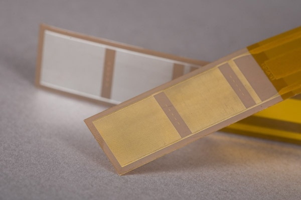
Figure 4. Disposable dielectric/conductivity sensor on polyimide flex circuit
This sensor is built as a Kapton® flex circuit, and is thin enough to be introduced between the plys of a laminate, and may be disposed of after use. A large A/D ratio of 160, with correspondingly high sensitivity, will be the result of the narrow electrodes, which are too small to be identified in the figure. The trade-off is measuring dielectric properties only within 100 µm of the surface.
A reusable dielectric/conductivity sensor embedded in a platen for a small press is shown in Figure 5. This sensor is built with interdigitated electrodes embedded in ceramic. It has an A/D ratio of 10. When installed as depicted, the sample can be placed, heated and compressed in the press, and dielectric measurements can be made simultaneously to monitor cure. This is followed by the removal of the sample from the sensor. The same process is then repeated.
Reusable sensors are ideal for QA/QC applications, where repetitive testing is common. Figure 5 shows the wider electrodes. This sensor can measure more deeply into the material, but has lower sensitivity due to the smaller A/D ratio.
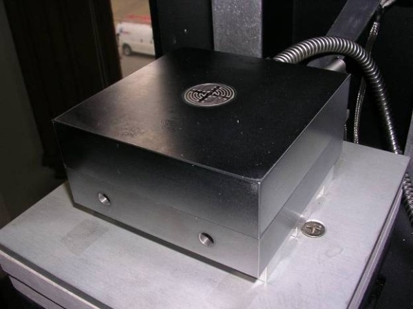
Figure 5. Reusable dielectric/conductivity sensor embedded in press platen
Conclusion
Parallel plate and interdigitated electrodes are the two general configurations of dielectric/conductivity sensors. The appropriate sensor is selected based on the desired sensitivity, as specified by the A/D ratio, and the desired type of measurement, whether bulk or surface.

This information has been sourced, reviewed and adapted from materials provided by Lambient Technologies.
For more information on this source, please visit Lambient Technologies.