Sponsored by EDAXJun 26 2015
Retained austenite plays a crucial role in determining the hardness, toughness, and strength of martensitic steel alloys. The quenching of these alloys forms a hard martensitic phase, but incomplete transformation can result in a retained austenite phase.

The presence of retained austenite is undesirable in certain applications such as tool steels and ball bearings because over time retained austenite can transform into martensite with a corresponding volumetric change that leads to expansion, dimensional changes, cracking, and failure.
In other applications, such as transformation induced plasticity (TRIP) steels, this transformation can be beneficial in improving the strength of an alloy. In both cases, measurements of the amount of retained austenite is a crucial step for optimizing the processing conditions of martensitic steel alloys in order to achieve the desired mechanical properties.
Drawbacks of Existing Solutions
Retained austenite measurements are traditionally obtained using X-ray diffraction (XRD). Other methods such as magnetic saturation or optical light microscopy typically provide complementary data to XRD.
XRD measurement standards assume a randomly textured sample, but most manufacturing processes create some amount of crystallographic texturing, limiting the accuracy of this assumption. XRD measurements need additional instrumentation to rotate or rock the sample to mitigate these effects.
XRD acquires data from a relatively large volume of material. The quenching and heat transfer behavior of complex shapes can lead to the formation of retained austenite only in specific locations. Neither XRD nor magnetic saturation provides the spatial location of the retained austenite within the analysis volume.
Carbides present within martensitic steels can produce overlapping peaks in XRD patterns that can interfere with retained austenite measurements. Therefore, additional analysis is required to identify the presence of carbides, and data collection routines must be modified to avoid carbide interference.
XRD systems with position-sensitive detectors require alloy-specific reference standards to calibrate retained austenite measurements to avoid significant errors.
To reveal the retained austenite structure, optical light microscopy requires chemical etching which may also differ in accordance with the alloy of interest. In addition, optical microscopy has limited spatial resolution.
Advantages of Electron Backscatter Diffraction (EBSD)
EBSD provides a fast and automated option to measure retained austenite content in martensitic steels.
Retained austenite content can be accurately measured even in highly textured samples. Both the crystallographic phase and orientation can be measured at each measurement point and phase measurements are not biased by a preferred orientation.
The spatial distribution of retained austenite can be mapped to see the location within the analysis area. This information is useful to gain an understanding of the local phase transformation behavior and to determine regions that may need different thermal processing to control the amount of retained austenite. Spatial distribution maps can also provide information on the shape and grain size of the retained austenite.
Combined EDS-EBSD ChI-ScanTM analysis provides direct identification of carbide phases within the microstructure. Carbide interference is eliminated thereby reducing ambiguity for retained austenite measurements.
Measurements are based on crystallographic parameters for constituent phases that do not need reference samples, making accurate retained austenite measurements easier and faster.
EBSD's high spatial resolution below 50nm allows small regions of retained austenite to be measured.
Microanalysis Results
Martensitic steels are used in a large number of applications and controlling the retained austenite is crucial for both the mechanical properties and service life of these materials.
This application example studies an inlet guide vane in a gas turbine engine. The vane directs the flow of the gas at the correct angle while controlling the mass flow and during operation, it is exposed to elevated levels of pressure and temperature.
Orientation maps of leading and training edge regions along the guide vane showing a tempered martensitic structure are presented in Figure 1.
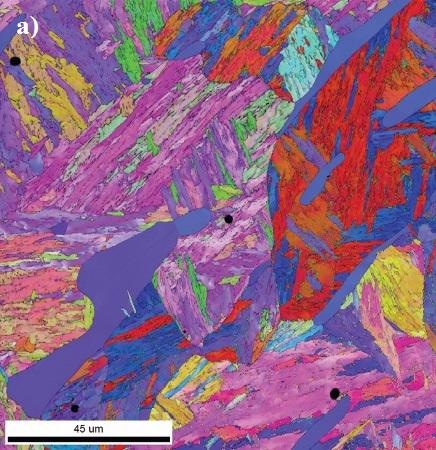
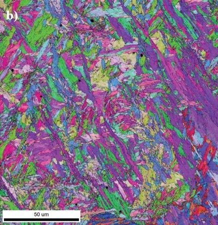
Figure 1. a) Leading edge EBSD orientation map. b) Trailing edge EBSD orientation map.
Phase maps of these regions with the martensite (shown in blue) and the retained austenite (yellow) are shown in Figure 2. The leading edge region has around 4% retained austenite content, compared to 2% in the trailing edge.
This suggests that the leading edge has a higher risk of failure due to the transformation of the retained austenite. The retained austenite in the leading edge analysis area is generally randomly distributed, whereas the trailing edge area shows a more segregated distribution, with the lower region having more retained austenite content than the upper region.
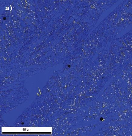
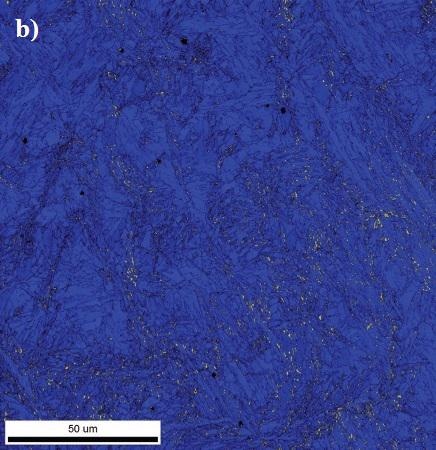
Figure 2. a) Leading edge phase map showing retained austenite distribution in yellow. b) Trailing edge phase map showing retained austenite distribution in yellow.
The EBSD phase maps clearly show the concentrated regions of retained austenite, which would not be observable with XRD analysis. These regions may be more vulnerable to distortions, cracking, and failure, and may indicate a heterogeneous heat transfer during quenching. Adjusting the heat-treating process may improve the retained austenite distribution and performance of the material.
Recommended EDAX Solution
Pegasus Analysis Systems are recommended to assist scientists and engineers to develop thermo-mechanical processing routines for controlling retained austenite content in order to optimize the performance, lifetime, and safety of steel components.
Pegasus Analysis Systems offer integrated EDS and EBSD characterization with a user-friendly interface for comprehensive analysis of material chemistry, phase distribution, and crystallography.

This information has been sourced, reviewed, and adapted from materials provided by EDAX, LLC.
For more information on this source, please visit EDAX.