A good combination of toughness, stiffness, and strength is required for fibers used in sophisticated applications, such as microelectronics, biomedical scaffolds, bulletproof vests, etc. However it is difficult to define these properties for nano- and micro-fibers due to their low stiffness. Also, most of the fiber’s chemical bonds are directed along the fiber axis due to the fiber drawing process, giving rise to a huge disparity in mechanical properties along the fiber axis as opposed to the perpendicular direction.
It is not possible to understand the properties of fibers from their bulk counterparts. Such differences can be particularly seen in smaller diameter fibers. For instance, electrospinning is one of the most commonly used techniques for fabricating very thin nano- and micro-fibers. Despite the significance, a large part of the studies that focus on mechanical properties have been restricted to defining the fibermats rather than separate fibers. In a recent study, however, Chen et al. reveals a considerable difference in the mechanical behavior of collagen-chitosan fibermats from that of the related individual fibers. Multiple studies carried out in the past few years, including the above reference, have shown different types of approaches to develop the electrospinning setup to collect aligned nano- and micro-fibers, which later can be transferred to templates for tensile testing using the KLA T150 UTM.
Tensile Test of Thin Fibers: Challenges and the T150 Advantage
Uniaxial tensile test is considered to be the most effective technique for the mechanical characterization of fibers. During the course of a tensile test, a sample of fiber is pulled at a given rate and the ensuing reaction force is determined.
Since the initial dimensions of the sample is already known, the measured force and displacement can be used to determine a number of major engineering parameters. Ultimate tensile strength, failure strain, yield strain, yield stress, and Young’s modulus are some of these parameters. Today, increasing amounts of fibers, particularly nano and micro-fibers are being recommended for structural applications, and tensile parameters are essential for better design and simulation of structures that use these kinds of fibers.
As the diameter of the fiber reduces, a fiber’s absolute stiffness also reduces considerably, and it becomes more difficult to determine the tensile parameters with traditional test instrumentation. In the case of a traditional tensile test system, the inertia and mass of the driveshaft and grips are relatively higher than fiber samples with smaller diameters.
While a fiber sample can be accommodated in a traditional tensile testing system, the precision of the results obtained is uncertain. These issues can possibly be prevented by understanding the thin fibers’ properties from a larger sample of the same material, such as woven/nonwoven fibermat or a yarn, which is a bundle of many fibers.
Conversely, this does not seem to be a credible characterization technique due to numerous nonelastic and elastic interactions between fibers and the differences in molecular alignment. The KLA T150 UTM has a gripping arrangement and a force range that are more suitable for determining fiber samples of small diameters.
When utilizing a nanomechanical tensile tester such as the KLA T150 UTM, a number of major components are behind the precise measurements. These components comprise of a patented nano-mechanical actuating transducer (NMAT) (Figure 1) that is capable of determining minute changes in force to give an exceptionally large dynamic force range for tensile measurements. An accurate extension axis helps to characterize fibers of small diameters at a broad range of strain rates.
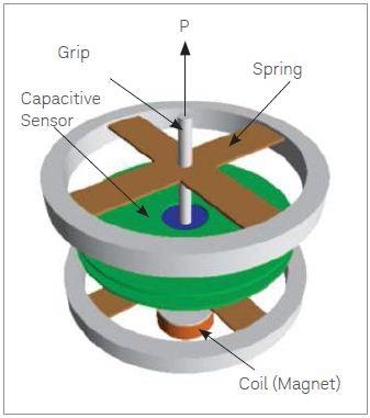
Figure 1. Schematic of nanomechanical actuating transducer (NMAT).
Further, the KLA NanoSuite control software meant for the T150 UTM enables accurate test control and data analysis and at the same time provides the ability to introduce novel test procedures for unique characterization of micro- and nano- fiber materials. Table 1 shows the technical specifications for the KLA T150 UTM.
Table 1. Technical specifications for the KLA T150 UTM.
| Maximum load |
500 mN (50.8 gm) |
| Load resolution |
50 nN (5.1 µgm) |
| Maximum actuating transducer displacement |
± 1 mm |
| Displacement resolution |
< 0.1 nm |
| Dynamic displacement resolution |
< 0.001 nm |
| Maximum crosshead extension |
200 mm |
| Extension resolution |
35 nm |
| Extension rate |
0.5 µm/s to 5 mm/s |
| Dynamic frequency range (sample dependent) |
0.1 Hz to 2.5 kHz |
Applications
Polymer Fibers
An engineering strain versus engineering stress curve for a PET fiber is shown in Figure 2. This was acquired by extending the fiber at a given strain rate. In this particular example, the fibers can be characterized across the entire range of strain via breaking, thanks to the large extension range of the KLA T150 UTM.
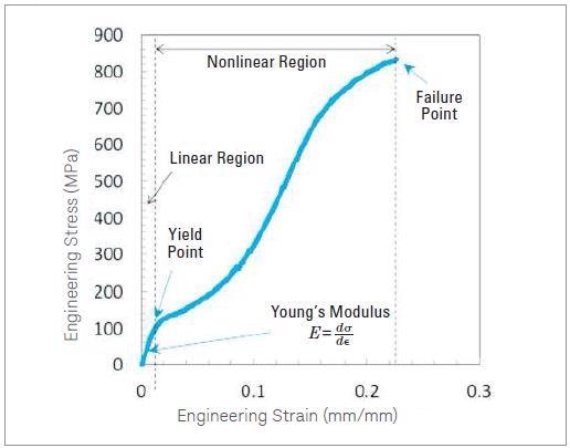
Figure 2. Engineering stress-strain curve for a PET iber (monoilament) of 17 µm diameter. Note the precise stress and strain measurements for the complete range of strain.
This proves particularly handy for thin polymeric fibers, where small amount of forces are needed for deformation and yet is capable of extending to large strains. Mechanical deformation properties of a polymer fiber like PET (Figure 2) can be understood by the so-called stress-strain curve. Many polymer chains are present in a polymer fiber and their physical properties control the fiber’s properties.
During the course of a tensile test, extension in a polymer fiber can be attributed to the non-elastic and elastic rotation of the chain axis towards the fiber axis as well as to the elastic extension of the polymer chains. Therefore, high modulus is exhibited by a polymer fiber having a slight orientation distribution of the polymer chains. Conversely, a polymer fiber’s strength relies on the nature of overlap between the polymer chains. This is because the strength of the van der Waals or physical hydrogen bonds between the polymer chains is relatively weaker as opposed to the covalent bonds present in the polymer chains.
Spider Silk
Spider silk is a unique material and is used in various biomedical and structural applications. Spiders have varied protein glands that create different types of silk having different arrangement of protein molecules. Spider silk serves as a complete tool for studying protein molecules and their arrangements, providing the special combination of high ductility and high strength. Conversely, it is very difficult to perform mechanical testing of separate silk strands in tension because of their high compliance and fine diameter. The KLA T150 UTM has a large dynamic range, which allows an obsolete stress-strain analysis of separate strands of spider silk with ultra high resolution.
A true strain versus true stress curve for a key ampullate silk strand acquired from a black widow spider is shown in Figure 3. In this thin fiber, the failure only occurs at a force of 2.5 mN. The more interesting fact is that the displacement resolution and high force of the KLA T150 UTM allows for accurate measurement of the complete stress-strain behavior, which shows four clear regimes. Owing to uniform stretching of amorphous molecules, regime I relates to the linear elastic response. During Regime II, the amorphous protein chains unfold, reducing the slope of the stress-strain curve. During Regime III, hardening occurs due to the alignment between the amorphous chains and the crystalline ß-sheets. In Regime IV, when the aligned molecular chains slip past each other, it causes a decrease in slope and ultimately leads to fiber failure.
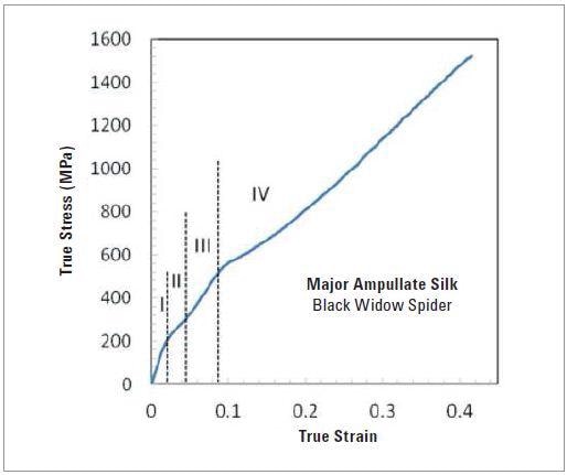
Figure 3. Typical tensile stress-strain behavior of major ampullate silk (diameter 1.8 μm) from Black Widow spider (collaboration with Jeff Yarger and Nik Chawla, Arizona State University).
Electrospun Fibers
Over the past few years, electrospinning has become a popular technique to produce micro and nano-fibers for use in biomedical scaffolds, filters, etc. Scientists are also attempting to create artificial fibers that share identical properties of the structures of natural fibers, such as spider silk. However in these applications, increased development of fiber and material architecture relies on the basic understanding of mechanical characteristics. The tensile reaction of thin electrospun poly-caprolactone (PCL) fibers as a function of diameter is shown in Figure 4.
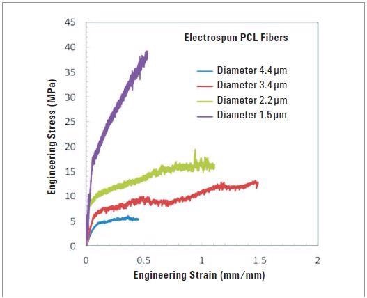
Figure 4. Engineering stress-strain curves for electrospun PCL ibers, showing variation of mechanical properties with fiber diameter (Collaboration with Frank Ko, University of British Columbia.)
The arrangement and crystallinity of the molecules inside an electrospun fiber are affected by a decreasing fiber diameter, often leading to an improvement of tensile strength and Young’s modulus. Since the T150 UTM has a very high force resolution, it helps in to measure µN level forces needed for deforming the thin fibers, and the precise measurement of Young’s modulus. Figure 4 precisely measures the increase in tensile strength and modulus with fiber diameter for electrospun PCL fibers.
Conclusion
The KLA T150 UTM can be used to determine the tensile characteristics of a range of small cross-sectional diameter fibers. The nanomechanical actuating transducer, which conforms to ASTM, offers an exceptional integration of displacement resolution and force, together with a huge extension range. These capabilities make the device perfect for defining spider silk, metal microwires, thin polymeric monofilaments, and numerous electrospun micro and nano-fibers.

This information has been sourced, reviewed and adapted from materials provided by KLA Corporation.
For more information on this source, please visit KLA Corporation.