Introduction A total hip replacement (THR) is a reconstructive procedure of the human hip joint. The hip joint occurs at the junction between the pelvis and the upper femur bone. A relatively large range of rotary motion is permitted at the hip by a ball-and-socket type joint; the top of the femur ends in a ball-shaped head that fits into a cuplike cavity known as the acetabulum. The artificial joint exists in various shapes, sizes, and brands. Doctors choose the appropriate one depending on the patient’s weight, size, health, bone quality, activity level, etc. A THR implant imitates in its design the natural hip it replaces. It has three parts, as illustrated in Figure 1: 1. A stem fits into the femur and provides stability 2. A ball takes the place of the spherical head of the femur, and 3. A cup replaces the worn-out hip socket. | 
| | Figure 1. Schematic of an artificial THR. | The stem and the ball are often combined to form a single unit. During the surgery, the doctor exposes the joint cavity through an incision. The damaged bone and cartilage of the femur and acetabulum are scrapped out and cleaned. The healthier tissues are left unscathed. In most cases, the head of the femur and the socket are replaced with artificial parts. A new metal cup is fixed firmly into the socket and the plastic ball is placed inside the cup. The implant stem is placed into the hollow center of the femur. There are two main types of total hip replacements (THR), which differ simply by method used to anchor the main components. In general, patients younger than 50 years of age will be outfitted with a press fit stem. This stem has a coating of hydroxyapatite spheres, which measure 10µm in diameter, and are deposited onto the surface of the stem and acetabular cup. This type of system does not utilize any cement due to the theory that there will be some degree of bone regeneration or growth into the hydroxyapatite coating in the young patient, providing the bond that will hold the prosthesis in place. On the other hand, there is the group of patients that will need the cemented hip replacement; patients older than 50, because their bodies are not able to produce the bone needed to hold the stem in place. Figure 2 shows the two types of stems described above. | 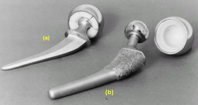
| | Figure 2. Types of stem used in total hip replacements: (a) cemented stem, and (b) press-fit stem. | Fixation of Artificial Hip Joints Early designs of total hip prosthesis used bolts and nuts to fix the femoral component to the femur, and metal pegs were used to fix acetabular component with metal-to-metal-bearing surfaces [1]. This technique of fixation and bearing surface were abandoned due to the massive tissue reaction by the wear particles released by the metal-on-metal friction between the cup and femoral head and destabilization of the femoral stem fixation. It is also possible that the stress concentration around the holes would have resulted in the failure of the fixation. Several years of intensive research and the work by Otto Röhm led to the birth of bone cements in the 1930s [2]. Two German companies, Degussa in Hanau, and Kulzer in Wehrheim, established a protocol for the chemical production of polymethylmethacrylate (PMMA) cement, which is an acrylic polymer. Since the introduction of bone cement for fixation of artificial hip joints by J. Charnley in the late 1950s, the procedure has been adopted throughout the world [2-6]. The initial success of the procedure in the total hip arthroplasties (THA) has been extended to the total knee arthroplasties (TKA), but success has been tempered by problems related not only to bone cement but also to the implants as such [7-11]. One of the inherent problems of orthopedic joint prosthesis implantation is the fixation and the maintenance of a stable interface between the device and the host tissue at the cellular and organ levels [12]. Loosening of the implant is especially important [13]. Many factors such as mismatch of the physical properties between tissues and implant, biocompatibility of the implant, deterioration of physical properties of implant materials, and problems with surgical techniques, design of the implant, selection of patients, and postsurgical care are related to the (late) loosening [14-16]. Cement Characteristics and Implant Insertion The success of THR largely depends on the quality of the bone cement utilized. The PMMA cement, commonly used, is primarily made of poly(methylmethacrylate) powder and methyl-methacrylate (MMA) monomer liquid as given in Table 1. Hydroquinone is added to prevent premature polymerization of the monomer which may occur due to exposure to light or elevated temperatures. N, N-dimethyl-p-toluidine is added to promote or accelerate curing of the polymerizing compound. Most commercial cements are prepared with an initiator (activator) of polymerization, benzoyl peroxide, and a radiopaque substance, either barium sulfate or zirconium dioxide, in addition to oligomers of PMMA itself. PMMA is obtained by the polymerization of the methylmethacrylate which is an exothermic reaction which continues until all monomer disappear producing long chain molecules. The monomer liquid will wet the polymer powder particle surfaces and link them by polymerization, resulting in a doughy substance which is injected into the prepared intramedurally cavity. Table 1. Bone Cement Components and Their Functions. | | | Liquid | Methyl methacrylate (monomer) | Wet PMMA particles | | N,N-dimethyl-p-toluidine | Polymerization accelerator | | Hydroquinone | Polymerization inhibitor | | Solid Powder | Polymethyl methacrylate | Matrix material | | Methyl methacrylate-styrene-copolymer | Matrix material | | Barium sulfate (BaSO4) | Radiopacifying agent | | Dibenzoyl peroxide | Polymerization initiator | Polymerization during curing obviously increases the degree of polymerization, that is, increases in molecular weight; however, the molecular weight distribution does not change significantly after curing. Studies show that bone cement properties can be affected by intrinsic factors (chemical composition of monomer and powder, powder particle characteristics, powder degree of polymerization, and liquid/powder ratio) and extrinsic factors (mixing environment: temperature and humidity, mixing technique: rate and number of beating with spatula and vacuum use, and curing environment: temperature, pressure and contacting surface). The most important factor controlling the acrylic bone cement properties is the porosity developed during curing or setting. Large pores are detrimental to the mechanical properties, monomer vapors and air trapped during mixing are two main reasons for porosity. The porosity can be reduced by exposure to vacuum and by reducing the temperature rise during polymerization [17]. Due to the cement chemical composition, the curing time of bone cements can be reduced, by preheating the femoral stem. This leads to decrease in surgery time and the potential risk of accidental loss of position [18]. Work done by Borzacchiello et al [19] concluded that amount of porosity in the cement was reduced at the cement implant-interface when the stem was heated to 44ºC, as compared to a stem inserted at room temperature. During implant insertion into the cement, air could be trapped at the implant cement interface; where the air entrapped has been found to vary with how fast the implant is inserted [20]. The air pockets dragged into the cement may form voids that lower the cement/implant interface strength, which can lead to premature failure. Vacuum mixing techniques, have been found to significantly reduce cement porosity, which leads to improved strength, and lowers the chance for a THR re-evaluation. In some investigations it has been reported that cement vacuum mixing produced a nine fold increase in cement fatigue life [21]. In contrast, hand mixing of the monomer and polymer involves folding the two components together and this introduces air. These air pockets then lower the cement and create locations for fracture initiation. Research on use of injection molding during manufacturing of the implant, to eliminate pores in cement, has shown reduction in cement cracking and debonding between cement and metal insert [22]. Analysis of the fracture surfaces of both monotonic and fatigue loaded bone cement samples of PMMA (polymethyl-methacrylate) show a classic cleavage step “river patterns” on all samples loaded monotonically, with “river patterns” running downstream in the direction of propagation of the crack [22]. Other mechanical processes used to improve the strength of the THR utilize implantation of foreign objects into the cement. One study [21] looked at imbedding a continuous stainless steel coil within the PMMA bone cement matrix, surrounding the distal tip of the total hip arthroplasty. A three dimensional finite element model depicting two and one half rotations of the coil imbedded within the cement at the distal tip was constructed. Ideally, the wire coil should reduce the radial, and largely, the hoop stresses. As a means of comparison, a control model of only bone cement was also built. The results of the study showed that for the radial stresses, the control cement-only model had about 4.5 times the compressive stress of the reinforced models at the cement-stem interface. The tensile hoop stresses were also 4.5 times higher for the control sample than for the reinforced models. This indicated that the wire coil reinforcement was effective in reducing the cement mantle's radial stress and, more importantly, the hoop stresses which may lead to the failure of both the cement and the implant as a whole [21]. The present study focuses on the insertion procedure of the implant into the cement, particularly with the objective of accelerating the surgical procedure without compromising the strength of the implant. The approach considered in this part of the investigation is that of preheating the implants as means to ease the introduction of the metal insert and speed up the polymerization and curing of the cement, to reduce the time for a THR. Experimental Procedure Preparation of Bone Specimens Full sized polymer artificial femurs consisting of a white spongy core region and a hard outer shell were used in this study, (Figure 3). The spongy material was reamed out of the bone to provide the cavity for the cement investigation. The femurs were sectioned approximately 76.2 mm (3 inches) below the lesser trochanter (Figure 4). From the lower portion of the lesser trochanter, down (distally), the bone was sectioned every 15.9 mm (0.625 inch) to obtain bone portions used for the fabrication of complete implant test specimens. That is, the cement was introduced into the medullary canal and the metal implant fit into the bone and cement; in addition, a portion of the implant sat above one of the faces that was designed to facilitate the machine contact to apply the load. The portion below the lesser trochanter was utilized since this region is where most fractures occur between the cement and the implant. Figure 5 shows the different stages in the fabrication of the implant specimen. Flat surfaces were machined 180º apart to assure a firm grip of the test specimen during the compression test. A cobalt-chromium alloy rod was used with a surface finish prescribed for implants. The rod was 9.53 ± 0.03 mm (0.375 ± 0.001 inch) in diameter and 25.4 mm (1.0 inch) in length. | 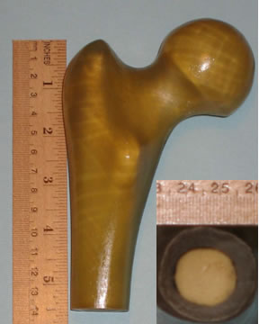
| | Figure 3. Artificial bone used in the present study. Inset photo shows bone cross section. | | 
| | Figure 4. Sketch showing details of the anatomy of the femur. | | 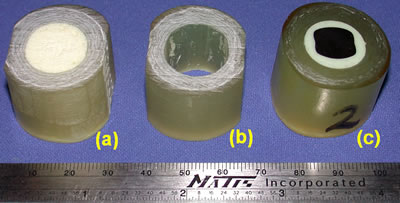
| | Figure 5. Stages of preparation of implant test samples: (a) original section of artificial femur, (b) reamed, and (c) final test sample. | The cement used in this study was a Palacos R with a composition described in Table 2. Batches containing 40 g of powder and 20 ml. of liquid monomer were mixed at one time, using a hand operated pump and a vacuum mixer. The vacuum pressure was maintained at 20 ± 2 torr, as recommended by the manufacturer. After the mixture was blended completely and thoroughly, with no visible air pockets or unmixed polymer powder, the vacuum was released. A custom shape spatula with a contour of the bottom portion of the bowl was later used to bring the cement that had moved to the outside rim back to the middle of the mixing bowl. During this time, much care was taken to make certain that no air pockets were introduced into the finished mixed cement, by means of aggressive mixing or folding over of the cement. Table 2: Composition of Cement used in this Study. | | | Methylmethacrylate-methylacrylate copolymer containing chlorophyll | 33.86-33.42 g | | Benzoyl peroxide, hydrous 75% | 0.20-0.64 g | | Zirconium dioxide | 5.94 g | | Liquid ( Monomer ) - 20 ml | | | Methylmethacrylate ( stabilized with hydroquinone) | 18.42 ml | | N,N-dimethyl-toluidine | 0.38 ml | | Chlorophyl | 0.4 ml | Once the cover of the mixing bowl is removed, there was limited time in which the cement may be worked to complete the insertion process, a total of three minutes is allowed to handle and inject the cement into the medullary cavity of the bone specimen. There were a total of 4 samples fabricated for the first cement batch and 3 specimens for the second batch. The most important step for producing consistent test specimens was the quick and accurate placement of the cement into the cavity of the bone, and the insertion of the stem into the cement bone complex. Prior to placing the cement into the cavity, the implant and bone sample that make part of the finished test specimens, were placed into the insertion fixture shown in Figure 6. Once the cement filled bone and the preheated implant were in the appropriate fixtures the male portion was pushed into the cement at a constant rate. Figure 7 shows the final test specimen that was submitted to compression testing. | 
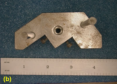
| | Figure 6. Fixture utilized for filling the cement and placing the metal insert into the bone sample medullary cavity. | | 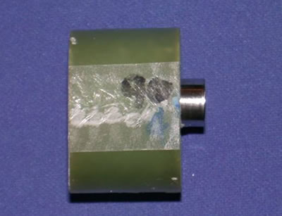
| | Figure 7. Completed implant specimen ready for compression test. | Shear Compressive Tests Since the objective of the study was to assess the effect of preheating temperature of the metal implant on the cement/metal implant interface strength. A number of implants were heated to three different temperatures: 50°C, 60°C, and 70°C before being inserted into the cement. There was a set of specimens that were produced with no preheating of the metal insert, to have a benchmark to compare the specimens that underwent preheating of the metal insert. The shear tests were carried out on an Instron 5500 Series tensile/compression test machine. The data was collected using data acquisition equipment. A fixture was fabricated for the compression shear test where the implant specimens rested; during the application of the load and when the metal insert separated form the cement it moved freely through the orifice of the fixture, as shown in Figure 8. A constant load rate was used for all test specimens. Following the mechanical tests the samples were evaluated microscopically, particularly the interface of the cement mantle in contact with the metal implant. | 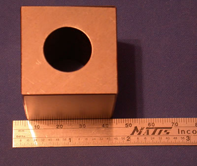
| | Figure 8. Fixture used for shear tests. | Results and Discussion Physical Characteristics of the Cement After the preparation of all sample implants for mechanical evaluation, the condition of the cement was evaluated in terms of its color appearance near the interface with the metal implant. This was done to establish if preheating might influence the chemical reactions occurring during curing and influence the cement condition. However, no cement discoloration or changes in the texture of the cement mantle between near the interface or away from it was observed. Bubbles or porosity could not be seen either near the surface of the finished samples before testing. Thus, based on macroscopic observations with the naked unaided eye, all samples were similar in appearance following their fabrication. Characterization of Implant Specimens without Preheat This group of samples was first characterized to institute a benchmark and thus establish the effect of metal insert preheating on the cement/metal insert interface strength. There were two batches of cement prepared for each of the temperatures of the metal insert; four specimens were produced from the first batch and three from the second. It was indicated in the previous section that the last sample was produced within the three minute time limitation recommended by cement manufacturers. This restriction comes in lieu of the fact that curing of the cement would almost start shortly after mixing of the ingredients. The shear compression test results for this group of implant specimens are shown in Figure 9. Curves 1-4 correspond to the same cement batch and curves 5-7 are part of the second cement batch. The numbers represent the order in which the implant specimens were fabricated. There was no time recorded for the specimen fabrication. | 
| | Figure 9. Compression shear test results for implants samples with no preheating of metal insert. | Figure 9 shows that Sample 1 had a higher maximum shear stress than Sample 2, and the subsequent samples had even lower values. The difference between the fabrications of these two samples is the time transpired from the end of the mixing of the cement to actual assembly of the implant test specimen. That is, during the additional elapsed time before insertion of the metal insert into Sample 2, there is likely additional polymerization and curing of the cement, which will influence the air drag as the metal rod slides through the mantle. In the first sample the cement would have lower viscosity, hence any large number of bubbles or cavities that may form during the sliding of the insert through the mantle would be filled easier by the more fluid cement mass. The mantles of the implant samples were examined after the compression tests at the cement/insert interface, as shown in Figure 10. The micrographs show the intimate contact that exists between the cement and the metal insert in view of the fine machining marks observed in the cement mantle. There were few and small air bubbles in Sample 1 (Figure 10a) compared to samples 2, 3, and 4 which were produced later. Figure 10b corresponds to the last sample of this batch, where more entrapped air was found, but also some of these air bubbles were larger and deformed. It is likely that the bubbles in the later sample were produced by the drag effect of the insert as it moved through the mantle during fabrication; as the polymer became harder, due to the longer curing time, the air bubbles created by the drag could not escape and the cement does not have the fluidity to fill such cavities. These results are consistent with what is reported in the literature that the air trapped in the cement, lowers the cement/insert interface strength, particularly the large pores. This is expected since there will be a reduction in the area of contact between the metal insert and the cement. | 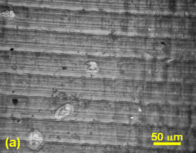
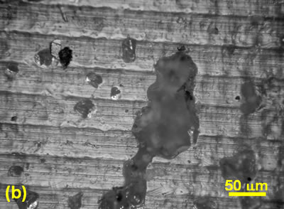
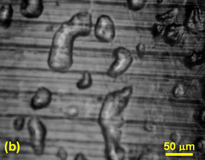
| | Figure 10. Micrographs describing the level of air entrapped in two implant samples of the same cement batch, fabricated at different times during the same production. (a) Sample 1 and (b) Sample 4. In these samples the metal insert was not preheated. | In the same Figure 9, curves 5, 6, and 7 correspond to samples of the second batch and their sequence also reflects the order of their fabrication. Similarly, the shear strength dropped with the delay of production time. Analysis of the cement surface in contact with the metal insert, once again show a larger amount of air entrapped for the last sample compared to the first specimen of the batch. Another observation made in examining the compression test results was that the group of specimens fabricated from the second cement batch had lower shear strength values than those from the first batch; for example Sample 1had maximum shear strength of 8.3 MPa compared to 6.7 MPa for Sample 5. These results suggest that despite the same experimental procedure used in the cement preparation, it is possible that subtle changes the mixing environments between the two batches might have occurred, such as the rate and number of cycles used in beating the cement mix, or perhaps small fluctuations in vacuum pressure. Effect of Implant Preheating on Interface Shear Strength The test results of the preheated implants showed the same tendency of the shear strength drop with increase in the delay time of sample production, as reported in the previous section. Figure 11 presents the results of specimens where the metal insert was preheated to 50ºC; samples 1-4 are part of the same batch, and samples 5-7 are part of the second cement batch for the same conditions. The evidence for such a drop is found in the condition of the cement at the interface with the metal insert. Figure 12 shows larger gas entrapment and larger air bubbles in Sample 4 compared to Sample 1 for the 50ºC insert preheat; as reported in the literature and described above, the presence of large pores has a detrimental effect of the cement/metal interface strength. In this group of samples it also appears that the mixing procedure could have an effect on the strength of the cement/metal interface; however the difference in shear strengths between the samples fabricated from the first batch compared to their counterparts of the second batch is not as large as found in the case of the implants produced with no preheating of the metal insert. Comparable results were obtained for the implant samples in which the metal inserts were preheated at 60 and 70ºC, that is, there was a decrease in interface strength with time of production for each batch. Figure 13 sums up the compression test results for samples produced with the metal insert preheated at 70ºC. | 
| | Figure 11. Shear stress strain graphs for the implant specimens in which metal insert was preheated to 50ºC. | | 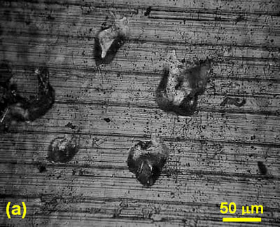
| | Figure 12. Micrographs describing the level of air entrapped in two implant samples of the same cement batch, fabricated at different times during the same production. (a) Sample 1 and (b) Sample 4. In these samples the metal insert was preheated at 50ºC. | | 
| | Figure 13. Shear stress-strain curves for the implant samples for which the metal was preheated to 70ºC. Curves 1-4 correspond to one cement batch, and curves 5-7 are for samples produced from the second cement batch in same fabrication. | Figures 9, 11, and 13 were compared in terms of the effect of preheating temperature of the metal insert on the maximum shear strength values, this comparison is summarized Figure 14. This plot was based on the maximum shear strength sample for each group. These results show that as the temperature increases the cement/metal interface shear strength decreases. This information suggests that the increase in temperature alters the curing process and thus accelerates the polymerization process. In addition higher temperatures would increase the porosity caused by the evolution of monomer vapors due to the exothermic reactions, in addition to the air trapped during mixing. It is indicated in the literature review that in some cases, due to the heat generated during the polymerization process, it is recommended to use some means to lower the temperature of the mix, because this tends to lower the level of porosity in the mix and hence increase the strength of the implant [17]. The interface surface of the tested samples was analyzed in terms of the air entrapped and other structure characteristics of the cement; there was much more porosity present at the 60 and 70ºC implant specimens compared to the other previous group of samples. Figure 15 show the characteristics of the cement in contact with the metal insert for a 70º C preheat. These results corroborate with the effect that the higher the temperature in the cement mix the higher the level of gas entrapped. In our studies we find then that the preheating f the insert does appear to speed up the curing process of the cement and hence shorten somehow the surgery, however, this procedure is not practical because it compromises the strength of the cement/metal interface of the implant. The results contract the work of Borzacchiello et al. [19] that found that the amount of porosity in a similar cement was reduced when the stem was heated to 44ºC, as compared to a stem inserted at room temperature. In the case of the 70ºC preheat samples, it was found that a crack developed in the cement of the last sample at the interface with the metal insert (Figure 15b); this implies that the cement is further along in its curing process and does not have the plasticity to deform as the metal insert is introduced into the mantle. | 
| | Figure 14. Maximum shear stress of the cement/metal insert interface as function of preheat temperature. | | 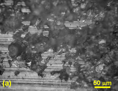
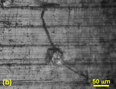
| | Figure 15. Surface appearance of the cement at the interface with the metal insert. For this implant specimen the preheat temperature was 70°C. (a) Extensive air entrapment, and (b) a crack developed in the cement of this sample during the introduction of the metal insert. | Conclusions 1. Preheating the metal implant had a negative impact on the soundness of a total hip replacement. 2. As the preheat temperature of the implant increased, the strength of the cement/metal implant interface was compromised. 3. The time between the end of mixing the cement and the fabrication of the implant will affect the strength of the interface. 4. The porosity developed at the cement/implant interface intensified with increase in preheat temperature. The 70ºC preheat caused the largest damage to the cement. 5. The processing techniques for mixing the cement impacts on the shear strengths of the implant specimens. This was established by the differences in strength of the samples from two different batches of the same condition. References 1. C. O. Bechtol, A. B. Ferguson and P. G. Laing, “Metals in Engineering Bone and Joint Surgery”, Williams & Wilkins. Baltimore, (1959). 2. Röhm & Haas, DE 642 289, (P. Weisert) 1935. 3. J. Charnley, “Acrylic Cement in Orthopedic Surgery”, Williams and Wilkins, Baltimore, (1970), 213-358. 4. J. Charnley, “The long-term results of low-friction arthoplasty of the hip, performed as a primary intervention”. J. Bone Joint Surg., 54B (1972) 61. 5. J. Charnley and Z. Cupic, “The Nine and Ten Year Results of the Low Friction Arthoplasty of the Hip”, Clin. Orthop. Rel. Res., 95 (1973) 9. 6. B. M. Wroblewski, “15-21 Year Results of the Charnley Low-Friction Arthoplasty”, Clin. Orthop. Rel. Res., 211 (1986) 30. 7. R. A. Brand, The Hip: “Non-Cemented Hip Implants”, Mosby, St. Louis, (1987) 213. 8. N. S. Eftekhar, “Principles of Total Hip Arthoplasty”, Mosby, St. Louis, (1978) 125-148. 9. D. C. Mears, “Materials and Orthopedic Surgery”. Williams and Wilkins, Baltimore, (1979) 602-603. 10. E. Morscher, “The Cementless Fixation of Hip Endoprosthesis”, Springer-Verlag, Heidelberg, (1984). 11. D. F. Williams and R. Roaf, “Implants in Surgery”. Saunders, London, (1973). 12. M. A. R. Freeman and R. Tennant, “The Scientific Basis of Cement versus Cementless Fixation”, Clin. Orthop. Rel. Res., 276 (1992) 19. 13. P. Ducheyne, “Prosthesis Fixation for Orthopedics”, Encyclopedia of Medical Devices and Instrumentation, Wiley-Interscience, New York, (1988) 2146-2154. 14. R. Crowninshield, “An Overview of Prosthetic Materials for Fixation”, Clin. Orthop. Rel. Res., 253 (1988) 166. 15. T. S. Gruen, G.M. McNeice and H.A. Amstutz, “Modes of Failure of Cemented Stem-Type Femoral Components”, Clin. Orthop. Rel. Res., 141 (1979) 17. 16. W. H. Harris and W. A. McGann, “Loosening of the Femoral Component after Use of the Medullary-Plug Cementing Technique”, J. Bone Joint Surg., 67B (1984) 222. 17. H.B. Lee and D. T. Turner, “Temperature Control of a Bone Cement by Addition of a Crystalline Monomer”, J. Biomed. Mater. Res., 11 (1977) 671. 18. N. E. Bishop, S. Ferguson and S. Tepic. “Porosity Reduction in Bone Cement at the Cement-Stem Interface”. J. Bone Joint Surg., 78B (1996) 349-356. 19. A. Borzacchiello, L. Ambrisio, L. Nicolais, E. J. Harper, E. Tanner and W. Bonfield, “Comparison between the Polymerization of a New Bone Cement and a Commercial One: Molding and in vitro Analysis”, Journal of Materials Science: Materials in Medicine, 9 (1988) 835-838. 20. G. Lewis and G. E. Austin. J. “Mechanical Properties of Vacuum-Mixed Acrylic Bone-Cement”, Appl. Biomater., 5 (1994) 307-314. 21. E. A. Friis, L. J. Stromberg, F. W. Cooke and D. A. McQueen, “Fracture Toughness of Vacuum Mixed PMMA Bone Cement”, 19th Annual Meeting of the Society for Biomaterials, Birmingham, AL, p. 301, (1993). 22. R. H. Dauskardt and K. L. Ohashi, “Effects of Fatigue Loading and PMMA Precoating on the Adhesion and Subcritical Debonding of Prosthetic-PMMA Interfaces”, J. Biomed. Mater. Res., 31 (1997) 172-183. Contact Details |