Introduction In science and technology of liquid crystals (LCs), the study of surface effects is one of the most significant and inevitable issues. LCs are very sensitive to the action of surface, which renders their interfacial phenomena [1]. Uniform alignment of LCs, which is a prerequisite in most liquid crystal displays (LCDs), is usually achieved by using anisotropic polymeric alignment films deposited on glass substrates. The aligning action is transposed from the substrate to the bulk LC via a specific interfacial interaction. The anisotropic surface–LC interaction by which the surface governs the orientation of the bulk is often termed surface orientational anchoring [2]. LCs are extremely sensitive to interface properties and the directors at the interface orient along the easy axis of the alignment layer. Hence, alignment layers are key components in LCDs. Homogeneous alignment occurs when the liquid crystal director aligns parallel to the substrate, whereas perpendicular alignment is referred to as homeotropic. The director axis exhibits a small uniform polar angle with the substrate in pretilted homogeneous alignment. Although the rubbing on polyimide layers remains the current technology for the large–scale production of LCDs, there is widespread interest in viable alternative technologies. One of the more attractive alternatives to rubbing is the generation of a surface anisotropy of an alignment film by photochemical means often called “photoinduced alignment” [3]. In general, photoinduced alignment is achieved by exposing a photoalignment polymer film with both unpolarized and polarized ultraviolet (UV) light. There are three main classes of materials that are used for photoalignment layers. They can be categorized according to the photochemical reaction responsible for the photoalignment, viz. (i) azo–containing polymers (photoalignment by reversible cis–trans isomerization), (ii) crosslinkable materials (photoalignment by photo–dimerization), and (iii) polyimides (photoalignment by photodegradation) [4]. Especially, surface alignment of photocrosslinkable PVCi film created with polarized laser light [5, 6] is a useful topic. The profound knowledge of the LC–surface interaction is essential and necessary to fully understand the surface engineering. The nature of the LC–surface interaction is complex and includes van der Waals interactions, dipolar interactions, steric factors, chemical and hydrogen bonding, and surface topography [7]. Which interaction plays a major role depends on the prevailing circumstances. Except for surface topographical part, all contributions are primarily governed by intermolecular interactions between substrate and LCs. Although a number of theoretical and practical efforts have so far been made in order to explain the surface anchoring, the underlying mechanisms are not yet clearly understood. The two classes of alignment mechanisms have been proposed for the surface anchoring. The first class is anisotropic LC orientational elasticity in connection with rubbing–induced microgrooves (surface topographic mechanism or elastic distortion model of Berreman) [8-10]. The second class is short–range interactions on the molecular scale [11-16]. In regard to the first class, Berreman proposed that the director field adapts itself to the topology of the substrate surface to minimize the elastic strain energy arising from the distortions of the director field. The second class is based on interactions between the LC molecules and the substrate. These interactions affect the orientational order of the LC molecules in the vicinity of the substrate; resultant LC molecular order in turn propagates toward the bulk via the intermolecular interactions which tend to align the molecules parallel to each other. That is, the bulk molecules exhibit epitaxial growth of nematic phase from the alignment surface [16, 17]. To understand the surface effect on the alignment of LCs better, many studies are focusing on the interfacial properties of LCs. Therefore, reliable characterization of surfaces and interfaces are demanded in surface science. Many type of tools for surface analysis have been developed over the years. However, most of their abilities have some limitations. Recently, several laser techniques have been developed for surface probing. Among these, optical second–harmonic generation (SHG) and vibrational spectroscopy by sum–frequency generation (SFG) have been proven to be effective tools for probing orientation and arrangement of surface molecular alignment [18-21]. In SHG technique, the signal increases with decreasing spot size for a given laser power but may be eventually limited by laser–induced surface damage. The problems involved in SHG technique are considerations about the size of the area to be probed, and the surface damage threshold of the material caused by laser heating [22]. Moreover, inside of the probed area should be uniform in regard to SHG technique because inhomogeneous surface area can generate the variations in SHG signal [23]. To overcome these problems, we have carried out this investigation by means of novel surface profiler instrument. | 
| | Figure 1. The photocrosslinking between two PVCi molecules under the irradiation of LPUV laser light. The vertical arrow E represents the polarization direction or polarization vector of incident electric field of linearly polarized UV light. | In this work, PVCi was used as a photoalignment layer. PVCi is the earliest synthetic photopolymer. Its design, a polyvinyl backbone with cinnamoyl side chains, was conceived in the hope that photocycloaddition between polymer-bound cinnamoyl groups would cross-link adjacent macromolecules [24]. It is well known and understood that the dominant photoreaction in PVCi is the (2 + 2) cycloaddition of two cinnamate side groups from different polymer chains to form a truxinic acid derivative as shown in Figure 1 [6, 27] i.e. PVCi shows a photo-dimerization reaction with polarized UV exposure [25, 26]. Prior to polarized UV exposure, the cinnamate acid side chains are isotropically distributed [5]. The cinnamate groups have significant UV dichroism and dielectric anisotropy due to electron delocalization extending from the benzene through the adjacent double bond to the carboxyl group. Therefore the absorption of a photon and the resulting cycloaddition is most probable when the photon polarization is in the direction shown in Figure 1 [6]. Polarized UV irradiation of an initially amorphous film will lead to a selective depletion of cinnamate groups aligned parallel to the polarization axis. It can be considered that, by using linearly polarized UV (LPUV) light, orientation-selective photo-reaction of PVCi molecules takes place, that is, LPUV light is selectively absorbed by PVCi molecules that have their side chains (cinnamate groups) parallel to the polarization vector of the polarized UV light and the molecules are dimerized. From considering the chemical structure of a PVCi molecule, the non-dimerized side chain has an elongated π-electron orbital along the side chain, and this anisotropic shape of the π-electron orbital gives a large refractive index (the slow axis) along the side chain. Therefore, the slow axis of a photo-exposed PVCi film are directing perpendicular to UV polarization, indicating a large population of non-dimerized side chains perpendicular to the UV polarization [25, 26]. Schadt et al. claim that LC alignment results from the anisotropic depletion of the cinnamate side chains as a consequence of the (2 + 2) cycloaddition reaction: the alignment direction of both the unreacted side chains and the principal photoproduct is perpendicular to incident UV field [4, 5]. Therefore, LCs align homogeneously on these films with their director oriented perpendicular to the direction of the polarization. The LC alignment on these PVCi surfaces were caused by the anisotropic van der Waals interaction between LC molecules and the optical anisotropy arising from the photoinduced side chain distribution [5, 6]. The purpose of this investigation is to study the surface alignment of LC multilayers formed by evaporation on photoalignment PVCi film. Visualization of a microscopic image was performed in the monolayer arrangement of LC molecules in contact with the surface of PVCi film. We aim to investigate the alignment of LC molecules on a periodically patterned substrate surface. The surface alignment of the evaporated LC multilayers on the PVCi film was investigated by means of the 3-D surface profiler and the optical polarizing microscope. | 
| | Figure 2. (a) Basic concept of the profile measurement; (b) Schematic diagram of 3-D surface profiler. | Concept of the 3-D surface profiler The alignment process of adsorbed LC monolayers on the surface of photoinduced PVCi alignment film can be imagined as a microscopic image. The surface topology of the LC multilayers was investigated by means of Scanning Laser Imaging Scope (Core System Co. Ltd.), which was the novel instrument for 3-D surface profile. Figure 2(a) depicts the fundamental concept of the profile measurement. Suppose a curved object with maintaining the distance l from the light source to the surface S. Scanning direction is along the x–axis. The surface profile of the measured object along the x–axis can be expressed by the function f(x). Let us assume that the light beam from the laser light source L is emitted on the curved object at the point P. When the angle θ with respect to the x–axis is much less than 1, the gradient at P can be expressed by:  (1) (1)
The angle between the incident light and the reflected light is approximated to 2θ, which corresponds to the deviation Δ from the incident light beam. Under such condition, Δ is approximated to 2θl. When the deviation Δ is measured by scanning object, the distribution function of the surface profile f(x) can be obtained by the measurement of Δ(x). From the equation (1), f(x) can be derived by:  (2) (2)
where α = ½l. The coefficient α can be determined by the calibration measurement with the known object. Sequential scanning with the two dimensional direction can provide the 3-D surface profile. The contrivance for surface profiler is illustrated in Figure 2(b). In this surface profiler, scanner mirror plays the role instead of scanning detector. This surface profiler was devised as such that the spherical concave mirror was combined for the purpose of synchronizing the curvature with optical intensity at the measured point. The remarkable feature of this instrument is its wide range of scanning area (~ 40 mm) with high vertical resolution (~ 0.01 nm). The detailed system diagram of the surface profiler and error analysis will be published elsewhere. Experimental Corning–1737F (Corning Co.) glass substrate was used for the experiment. Polyvinylcinnamate (PVCi) [Avg. Mw ca. 200,000 (GPC), 1wt%, Aldrich Chem. Co.] was used for photoalignment layer and was spin coated on the glass substrate and then dried at 90°C for 30 sec. Figure 3 illustrates the experimental configuration for the generation of striped alignment patterns on sample. The periodically striped patterns were produced by using He–Cd laser (Kimmon, K3501R-G) [λ = 325 nm, 25 mW/cm2] with a photo–mask (100 μm line and space). The exposure time was set to be 20 min. To verify the flatness of PVCi film on the substrate, atomic force microscope (AFM) (Shimadzu, SPM–9500J2) was used. For evaporation, 4′-n-pentyl-4-cyanobiphenyl (5CB, supplied by Merck) [TNI =35.5°C] was heated on a hot plate at 90°C and then, adsorbed on the substrate surface positioned 5 cm from the LC source at room temperature in air. Amounts of the 5CB adsorption were controlled by changing the duration of evaporation. | 
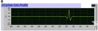
| | Figure 3. Experimental setup for periodical striped pattern formation. | Results and Discussion Figure 4 shows 3-D surface height pattern mapping of photoinduced PVCi film revealed by the surface profiler. It was found as indicated in Figure 4 (b) that the surface of the PVCi film revealed no surface relief gratings. To complement this result, AFM images of the PVCi film were taken with dynamic mode as shown in Figure 5. We used 20 μm photo–mask instead of 100 μm photo–mask because the scanning range of our AFM was 30 × 30 μm2. The resultant surface of the PVCi alignment film revealed no periodical surface having relief gratings, while shallow wrinkle caused by the spin coating was found. | 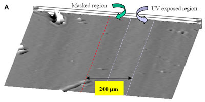
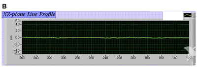
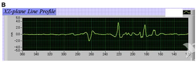
| | Figure 4. Pattern mapping of photoinduced PVCi film revealed by the surface profiler. (a) The periodical striped patterns (100 μm UV exposed and masked regions) of PVCi film in the horizontal direction; (b) The vertical height resolution of (a). | | 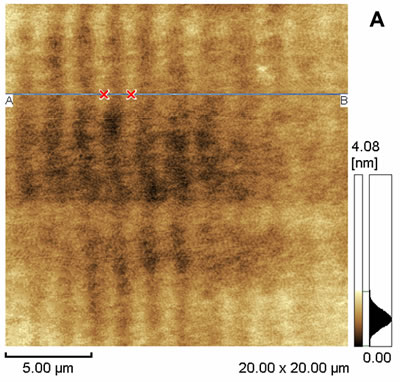
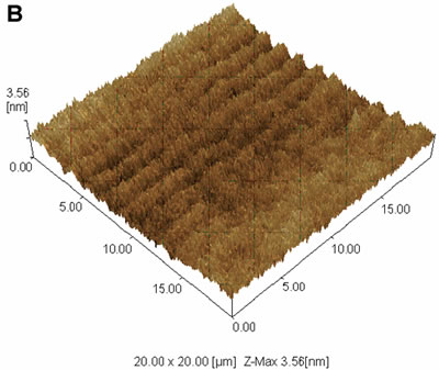
| | Figure 5. 20 × 20 μm2 dynamic mode AFM images of the surface of PVCi film. (a) 2-D display of the AFM data; (b) 3-D display of the AFM data. | Figures 6–8 show 3-D surface height pattern mappings of the LC multilayers formed by evaporation on photoinduced PVCi film by changing evaporation duration for 1, 2, and 3 hours, respectively. | 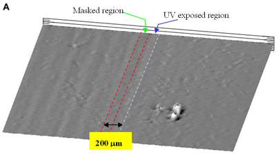
| | Figure 6. 3-D surface height pattern mapping of the LC multilayers formed by evaporation on photoinduced PVCi film revealed by the surface profiler for 1 hour 5CB evaporation. A surface topology with a few angstrom surface roughness was observed in both UV exposed region and the masked region. (a) The periodical striped patterns (100 μm UV exposed and masked regions) of LC multilayers in the horizontal direction; (b) The vertical height resolution of (a). | | 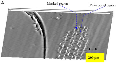
| | Figure 7. 3-D surface height pattern mapping of the LC multilayers formed by evaporation on photoinduced PVCi film revealed by the surface profiler for 2 hours 5CB evaporation. Vertical height information: ≈ 0.5 nm for UV exposed region and 1.5 – 4.5 nm for the masked region. A burrow in the left side of the pattern mapping is a mechanical damage of the film. (a) The periodical striped patterns (100 μm UV exposed and masked regions) of LC multilayers in the horizontal direction; (b) The vertical height resolution of (a). | | 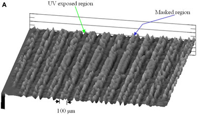
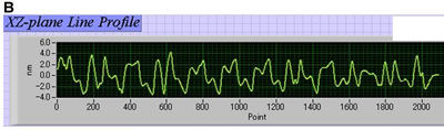
| | Figure 8. 3-D surface height pattern mapping of the LC multilayers formed by evaporation on photoinduced PVCi film revealed by the surface profiler for 3 hours 5CB evaporation. Vertical height information: 1.5 – 3 nm for UV exposed region and 4.5 – 8 nm for the masked region. (a) The periodical striped patterns (100 μm UV exposed and masked regions) of LC multilayers in the horizontal direction; (b) The vertical height resolution of (a). | From these pattern mappings, we can imagine the following picture for the alignment process of adsorbed LC on the photoinduced PVCi alignment film surface. The surface density of LC molecules was quite low at 1 hour duration because few LC molecules were adsorbed and covered on the full surface area. With increasing the evaporation time, the revealed image presented that the surface density of LC molecules became increased. At 3 hours duration, a periodic profile was clearly seen on the surface, where the period corresponded to the photo–mask pattern with 100 μm line and space. It was also recognized that the pattern height of the UV exposed region was lower than that of the masked region. This result implies that the LC molecular alignment on the surface occurred at the masked region was voluminous compared with that at the UV exposed region. On the other hand, it was known that the LC molecules on the surface occurred at the UV exposed region were well aligned parallel to the substrate surface along the direction, which was perpendicular to the irradiated UV polarization [5, 6]. Besides, the pattern indicated that layer–by–layer nematic growth would likely form homogeneous alignment [31-34]. In the masked region, however, LC molecular order was fairly low. Therefore, randomly oriented LC molecules seemed to make the LC multilayers voluminous. We proposed a possible model of surface molecular alignment of the LC multilayers at both the UV exposed region and the masked region as illustrated in Figure 9. This model was based on the concept of the anisotropic van der Waals interaction between LC molecules and the optical anisotropy arising from the photoinduced side chain distribution on the PVCi films. There are theoretical arguments for van der Waals contribution to the surface and anchoring energies of nematic LCs [7, 28, 29]. Based on such existing theories, Schadt et al. proposed that the LC alignment on photoinduced PVCi surfaces were caused by anisotropic van der Waals interaction between LC molecules and the optical anisotropy arising from the photoinduced side chain distribution [5]. Moreover, from other relevant experimental results, it can be realized that one of the dominant forces to align LC molecules on the photoinduced PVCi film comes from the anisotropic van der Waals interaction [6, 25-27, 30]. In this model, we assumed that the bulk molecules exhibit epitaxial growth of nematic phase from the alignment surface in accordance with the second class of alignment mechanisms (molecular epitaxy-like model) because the AFM result (Figure 5) showed that the surface of the photo-treated PVCi film revealed no surface relief gratings (so that surface topographical contribution can be excluded). | 
| | Figure 9. A possible model for explaining the surface molecular alignment of LC multilayers at both the UV exposed region and the masked region. The Cartesian–coordinate system is defined by using the molecular layer as the x–y plane, and the z–axis as the layer normal. Here, θ is the angle between the molecular axis n and the layer normal, and φ is the azimuth angle of the molecular axis in the plane of the layer. The cans represent LC orientation. | With these ideas in mind, we hope that it will be easy to understand the proposed model depicting different alignment mechanisms on photo-treated patterned PVCi surface as illustrated in Figure 9. In the UV-exposed region, LC molecules are well aligned parallel to the substrate surface along the direction, which is perpendicular to the irradiated UV polarization resulting in the formation of low alignment profile. In the masked region, LC molecules are randomly oriented due to the isotropic distribution of surface polymer molecules (i.e. the cinnamate acid side chains) thereby making LC alignment profile voluminous. Thus, it can be concluded that the height difference in alignment profile between the UV-exposed region and the masked region comes primarily from the anisotropic van der Waals interaction between LC molecules and optically anisotropic PVCi film. In order to complement our consideration, polarized microphotographs of the evaporated LC multilayers on photoinduced PVCi film are shown in Figure 10. Periodic image was clearly seen on the surface. In the UV exposed region, a planar alignment with nematic schlieren texture was found whereas the masked region appeared dark due to random alignment. From Figure 10, it was realized that the polarized microphotographs confirmed the proposed model of surface molecular alignment. In the polarized microphotographs, no vertical information was found. Therefore, this point is strongly useful for the novel surface profiler in which nanoscale profile was achieved with millimeter wide range. | 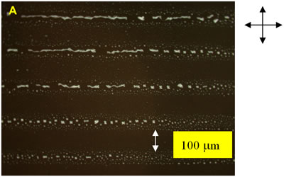
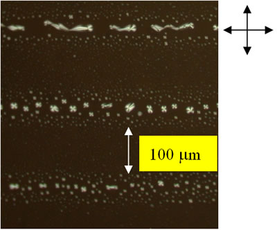
| | Figure 10. (a) Polarized microphotograph of the surface alignment of the evaporated LC multilayers on photoinduced PVCi film for 3 hours 5CB evaporation. The substrate is between crossed polarizers. (b) Magnification of (a). | Conclusions The topology of evaporated LC multilayers on the surface of photoinduced PVCi film was visualized for the first time by means of the novel surface profiler instrument. It was found that the height of LC multilayers in the UV exposed region was lower than that in the masked region. This height difference revealed the different alignment mechanisms for the exhibited periodic profile. It seemed likely that the topology of LC multilayers reflected the orientational distribution of LC molecules on the film. The optical polarizing microscopy confirmed that there was a planar alignment with nematic schlieren texture in the UV exposed region. It was realized that the photoinduced PVCi surface can effectively align adsorbed LC multilayers towards the direction parallel to the substrate surface, and then the alignment can be extended to the bulk via the epitaxy-like LC–LC interaction. From the practical viewpoint, the open–air molecular deposition on artificially patterned alignment film can be a potential technique to realize a functional surface. As a molding technique, the basic concept is quite unique compared with the printing technique, because the open–air molecular deposition can be looked upon as a non–contact molding technique. The resolution and height control is the next challenge and will be reported elsewhere. Acknowledgement This work was partially supported by a Grant–in–Aid for Encouragement of Young Scientists (B) (No. 15760020) from Japan Society for the Promotion of Science. References 1. A. A. Sonin, “The Surface Physics of Liquid Crystals”, Gordon and Breach, Amsterdam (1995) pp. x–xi. 2. B. Jerome, “Surface effects and anchoring in liquid crystals”, Rep. Prog. Phys., 54 (1991) 391–451. 3. W. M. Gibbons, P. J. Shannon, S. –T. Sun and B. J. Swetlin, “Surface–mediated alignment of nematic liquid crystals with polarized laser light”, Nature, 351 (1991) 49–50. 4. M. O’Neill and S. M. Kelly, “Photoinduced surface alignment for liquid crystal displays”, J. Phys. D: Appl. Phys., 33 (2000) R67–R 84. 5. M. Schadt, K. Schmitt, V. Kozinkov and V. Chigrinov, “Surface–Induced Parallel Alignment of Liquid Crystals by Linearly Polymerized Photopolymers”, Jpn. J. Appl. Phys., 31 (1992) 2155–2164. 6. G. P. Bryan-Brown and I. C. Sage, “Photoinduced ordering and alignment properties of polyvinylcinnamates”, Liq. Cryst., 20 (1996) 825–829. 7. K. Okano, N. Matsuura and S. Kobayashi, “Alignment of a Liquid Crystal on an Anisotropic Substrate”, Jpn. J. Appl. Phys., 21 (1982) L109–L110. 8. D. W. Berreman, “Solid Surface Shape and the Alignment of an Adjacent Nematic Liquid Crystal”, Phys. Rev. Lett., 28 (1972) 1683–1686. 9. D. W. Berreman, “Alignment of Liquid Crystals by Grooved Surfaces”, Mol. Cryst. Liq. Cryst., 23 (1973) 215–231. 10. S. Faetti, “Azimuthal anchoring energy of a nematic liquid crystal at a grooved interface”, Phys. Rev., A 36 (1987) 408–410. 11. J. M. Geary, J. W. Goodby, A. R. Kmetz and J. S. Patel, “The mechanism of polymer alignment of liquid–crystal materials”, J. Appl. Phys., 62 (1987) 4100–4108. 12. D. Johannsmann, H. Zhou, P. Sonderkaer, H. Wierenga, B. O. Myrvold and Y. R. Shen, “Correlation between surface and bulk orientations of liquid crystals on rubbed polymer surfaces: Odd–even effects of polymer spacer units”, Phys. Rev., E 48 (1993) 1889–1896. 13. H. Kikuchi, J. A. Logan and D. Y. Yoon, “Study of local stress, morphology, and liquid–crystal alignment on buffed polyimide surfaces”, J. Appl. Phys., 79 (1996) 6811–6817. 14. J. Cheng and G. D. Boyd, “The liquid–crystal alignment properties of photolithographic gratings”, Appl. Phys. Lett., 35 (1979) 444–446. 15. R. Barberi, I. Dozov, M. Giocondo, M. Iovane, Ph. Martinot–Lagarde, D. Stoenescu, S.Tonchev and L. V. Tsonev, “Azimuthal anchoring of nematic on undulated substrate: Elasticity versus memory”, Eur. Phys. J., B 6 (1998) 83–91. 16. M. B. Feller, W. Chen and Y. R. Shen, “Investigation of surface–induced alignment by liquid–crystal molecules by optical second–harmonic generation”, Phys. Rev., A 43 (1991) 6778–6792. 17. M. Barmentlo, R. W. Hollering and N. A. J. M. van Aerle, “Correlations between surface and bulk liquid–crystal alignment observed with optical second–harmonic generation”, Phys. Rev., A 46 (1992) R4490–R4493. 18. Y. R. Shen, “Surface properties probed by second–harmonic and sum–frequency generation”, Nature, 337 (1989) 519–525. 19. Y. R. Shen, “Optical second harmonic generation at interfaces”, Annu. Rev. Phys. Chem., 40 (1989) 327-350. 20. W. Chen, M. B. Feller and Y. R. Shen, “Investigation of Anisotropic Molecular Orientational Distributions of Liquid–Crystal Monolayers by Optical Second–Harmonic Generation”, Phys. Rev. Lett., 63 (1989) 2665–2668. 21. C. S. Mullin, P. Guyot–Sionnest, and Y. R. Shen, “Properties of Liquid–Crystal Monolayers on silane surfaces”, Phys. Rev., A 39 (1989) 3745–3747. 22. G. T. Boyd, Y. R. Shen, and T. W. Hänsch, “Continuous–wave second–harmonic generation as a surface microprobe”, Opt. Lett., 11 (1986) 97–99. 23. K. Pedersen and S. I. Bozhevolnyi, “Second–Harmonic Generation Scanning Microscopy on Domains in Al Surfaces”, Phys. Stat. Sol., (a) 175 (1999) 201-206. 24. P. L. Egerton, E. Pitts, and A. Reiser, “Photocycloaddition in Solid Poly (vinyl cinnamate). The Photoreactive Polymer Matrix as an Ensemble of Chromophore Sites”, Macromolecules, 14 (1981) 95-100. 25. Y. Iimura, S. Kobayashi, T. Hashimoto, T. Sugiyama, and K. Katoh, “Alignment Control of Liquid Crystal Molecules using Photo-Dimerization Reaction of Poly (Vinyl Cinnamate)”, IEICE Trans. Electron, E79-C (1996) 1040-1046. 26. X. T. Li, H. Saitoh, H. Nakamura, S. Kobayashi, and Y. Iimura, “Mechanism of Photo-Induced Liquid Crystal Alignment on Poly (vinyl cinnamate) Surface”, J. Photopolym. Sci. Technol., 10 (1997) 13-18. 27. R. Karapinar, M. O’Neill, S. M. Kelly, A. W. Hall and G. J. Owen, “Molecular alignment of liquid crystals on a photosensitive polymer surface exposed to linearly polarized ultraviolet laser radiation”, ARI, 51 (1998) 61-65. 28. K. Okano and J. Murakami, “van der Waals dispersion force contribution to the interfacial free energy of nematic liquid crystals”, J. Phys. (Paris) Colloq., 40 (1979) C3-525-528. 29. J. Bernasconi, S. Strässler and H. R. Zeller, “van der Waals contribution to the surface and anchoring energies of nematic liquid crystals”, Phys. Rev., A 22 (1980) 276–281. 30. X. T. Li, D. H. Pei, S. Kobayashi and Y. Iimura, “Measurement of Azimuthal Anchoring Energy at Liquid Crystal/Photopolymer Interface”, Jpn. J. Appl. Phys., 36 (1997) L432-L434. 31. T. Shioda, Y. Okada, D. –H. Chung, Y. Takanishi, K. Ishikawa, B. Park and H. Takezoe, “Liquid Crystals Align Liquid Crystals”, Jpn. J. Appl. Phys., 41 (2002) L266–L268. 32. B. Jérôme and Y. R. Shen, “Anchoring of nematic liquid crystals on mica in the presence of volatile molecules”, Phys. Rev., E 48 (1993) 4556–4574. 33. M. Woolley, R. H. Tredgold and P. Hodge, “Ultrathin Films of Smectic Liquid Crystals on Solid Substrates”, Langmuir, 11 (1995) 683-686. 34. I. D. Olenik, K. Kočevar, I. Muševič and Th. Rasing, “Structure and polarity of 8CB films evaporated onto solid substrates”, Eur. Phys. J., E 11 (2003) 169–175. Contact Details |