In order to be able to offer the best machine for each requirement, Zwick‘s comprehensive product range includes three machine versions for static materials testing, each of them offering different equipment, performance and expansion capabilities:
- The zwicki-Line consists of top quality space-saving testing machines. These simple-to-use and easy-to-transport single column machines have been designed for test forces up to a maximum of 2.5 kN.
- The ProLine is particularly suitable for functional tests on component parts as well as for standard materials tests. A broad range of standard accessories provides comprehensive testing capability at an affordable price.
- The Allround-Line is the flagship range of testing equipment offering the highest level of technical sophistication and future expansion possibilities.
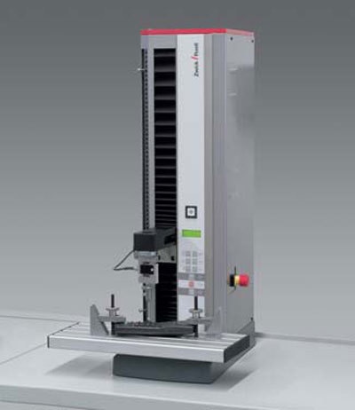
Figure 1. The ProLine materials testing machines for materials, component and component functionality testing
Measurement and Control System
The fundamental component for any testing machine is the measurement and control system. Its design and scope of capabilities determine which drive system it can regulate, which measurement system it is connected to and which functions can be controlled. The testControl controller offers highest technical performance and long range return of investment through the use of the latest technologies and highest quality standards. Notable characteristics of the electronics are:
- Chronologically-synchronized test data recording with high resolution and measurement frequency
- Sampling of input signal at 320 kHz 500 Hz real-time processing of the test data for monitoring and event oriented control of the test sequence and for safety limits. (e.g. speed change upon reaching the yield or proof stress limit)
- Adaptive control for precise and reproducible speeds and positions testControl and hence the testing machine, is operated by using a PC and the test software testXpert® II.
The system is easy to configure and upgrade for almost any diverse application as well as extremely flexible and easy to operate. The optional stand-alone variant offers simple, direct operation of the testing machine without a PC, using a colour display, a key pad and a few, intuitive function keys. A printer can be connected to output the test results.
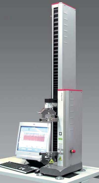
Figure 2. Extended-height load frame version for testing of plastic film
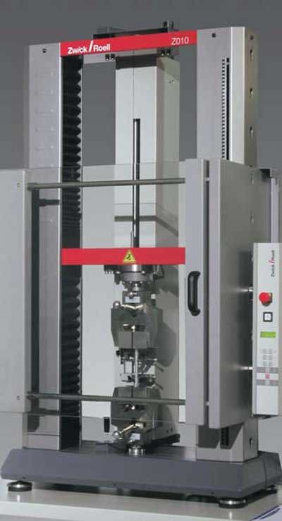
Figure 3. Materials testing: tensile test according to ISO 527-2
Load Frames
Different load frame versions are available for test loads up to 2000 kN as standard. Special applications can be developed and manufactured, e.g. load frames in horizontal position suitable for the testing of long ropes.
Table 1. zwicki-Line load frames and drives
|
Series
|
Z1.0
|
Z2.5
|
|
Max. test load [kN]
|
1.0
|
2.5
|
|
Work space height
|
|
|
|
short [mm]
|
-
|
573
|
|
normal [mm]
|
-
|
1073
|
|
high [mm]
|
1373
|
1373
|
|
Work space width [mm]
|
x
|
x
|
|
Work space depth [mm]
|
99.5
|
99.5
|
|
Max. crosshead speed [mm/min]
|
1800
|
800
|
|
Crosshead travel resolution [ìm]
|
0.2265
|
0.0996
|
|
Max. power consumption, kVA
|
0.4
|
0.4
|
Table Top Testing Machines, zwicki-Line
These single column load frames are designed with very-rigid aluminium high-precision extruded profiles. The working area is freely accessible from 3 sides. It only requires limited bench space and fits on most laboratory tables. Due to its low weight, it is easy to transport.
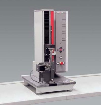
Figure 4. zwicki-Line materials testing machine in a short version
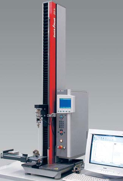
Figure 5. zwicki Z2.5 equipped with appropriate fixturing to determine the coefficients of friction (COF)
Table Top Testing Machines, ProLine
The load frames of the ProLine are designed with twin lead screws and 2 round steel columns ensuring precise guidance of the moving crosshead. The integrated protection of lead screws and guide columns aids reliable testing even for very brittle materials.
A single column version is available within the ProLine range for testing at forces of up to 500 N.
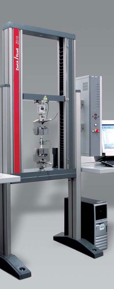
Figure 6. Allround-Line Z010 equipped for tensile testing
Table Top and Floor Standing Models, Allround-Line
The table-top version is constructed using two aluminium, high-precision extruded profiles (patented design). They are light, very rigid and serve simultaneously as lead-screw guides and protection. T-shaped grooves on the outer sides allow a simple fitting of accessories as e.g. safety devices without being impeded by the crosshead.
A unique development by Zwick allows all table top load frames with two columns to be equipped with legs to allow them to stand on the floor and position the working area at an optimum height for the operator. This allows a comfortable seated operation with complete freedom for leg movement thus making the testing system suitable for wheelchair users.
The floor standing models are equipped with hard-chrome plated steel guiding columns and high precision and backlash-free ball screws. The crossheads of these loadframes can be arranged in different ways, so that the lower, upper, or both workspaces can be utilized.
All load frames with an electromechanical drive system can be equipped with a second working area. This allows a fast and convenient work station and can eliminate the need for the operator to change tooling and operator.
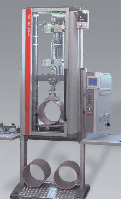
Figure 7. Allround-Line Z050 in an extended version for testing tensile characteristics and ring stiffness on plastic pipes
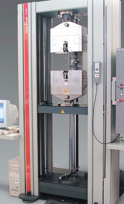
Figure 8. Allround-Line Z100 equipped with pneumatic grips and Macro extensometer
Drives
Electromechanical Drives
All electromechanical drives are based on play-free and low-wear ball-type linear drives and digitally controlled drives. They are equipped with load frames for test loads up to 600 kN. Combined with digital measurement and control systems, they offer the following advantages:
- Extremely-large, infinitely-variable speed range
- Very-low speed settings possible (from about 0.5 ìm/min)
- Highly precise and exactly reproducible positioning
Hydraulic Drives
This drive is located in the center of the upper fixed crosshead. The workspace below is therefore easily accessible. A servo or proportional valve regulates the oil flow between the hydraulic unit and differential cylinder. The oil cushion in the upper pressure prevents plunger pistons from “jumping” when a specimen breaks. The resolution of the piston travel sensor is 1.25 ìm (less than 1/400,000th of the maximum testing travel. The hydraulic drive is the most efficient solution particularly for large test loads.
Hybrid Drives
These patented drives combine the advantages of the electromechanical drive (high position accuracy) and with those of the hydraulic drive (high-force capacity, low wear, robust unit). The result is a test machine which has very-high force capacity can be used to measure and accurately control small displacements. This is accomplished by utilizing two parallel, synchronized hydraulic cylinders coupled with the machine crosshead, which follow precisely the positions specified by the electromechanical pilot drive. The special features of this drive are:
- Large crosshead travel range (no adjustment of the fixed crosshead necessary)
- Relatively low-construction height allowing easier installation
Table 2. ProLine Load Frames and Drives
|
Model
|
Z0.5
|
Z005
|
Z010
|
Z020
|
Z030
|
Z0501
|
Z100
|
|
Max. test load [kN]
|
0.5
|
5
|
10
|
20
|
30
|
50
|
100
|
|
Work space height
|
|
|
|
|
|
|
|
|
shortened [mm]
|
-
|
570
|
-
|
-
|
-
|
-
|
-
|
|
normal [mm]
|
590
|
1070
|
1050
|
1050
|
1370
|
1370
|
1360
|
|
increased [mm]
|
1360
|
-
|
-
|
-
|
-
|
-
|
-
|
|
Work space width [mm]
|
4
|
440
|
440
|
440
|
440
|
440
|
640
|
|
Work space depth [mm]
|
100
|
4
|
4
|
4
|
4
|
4
|
4
|
|
Max. crosshead speed [mm/min]
|
1500
|
500
|
1000
|
500
|
300
|
180/6001
|
300
|
|
Crosshead travel resolution [ìm]
|
0.226
|
0.039
|
0.095
|
0.047
|
0.025
|
0.015/0.0161
|
0.008
|
|
Max. power consumption, kVA,
|
0.4
|
0.8
|
0.8
|
0.8
|
0.8
|
0.8/31
|
3
|
1 This testing machine is available in two drive / speed options
Table 3a. Allround Line Load Frames and Drives – Tabletop Testing Machines
|
Model
|
Z005
|
Z010
|
Z020
|
Z030
|
Z050
|
Z100
|
Z150
|
|
Max. test load [kN]
|
5
|
10
|
20
|
30
|
50
|
100
|
150
|
|
Work space height
|
|
|
|
|
|
|
|
|
normal [mm] 2
|
1045/1025
|
1045/1025
|
1045/1025
|
-
|
-
|
-
|
-
|
|
increased [mm] 2
|
1445/1425
|
1445/1425
|
1445/1425
|
1355
|
1355
|
1355
|
1535
|
|
extra high [mm] 2
|
1795/1785
|
1795/1785
|
1795/1785
|
-
|
-
|
1755
|
-
|
|
Work space width
|
|
|
|
|
|
|
|
|
normal [mm]
|
440
|
440
|
440
|
440
|
440
|
-
|
-
|
|
widened [mm]
|
640
|
640
|
640
|
-
|
-
|
640
|
640
|
|
Work space depth [mm]
|
4
|
4
|
4
|
4
|
4
|
4
|
4
|
|
Max. crosshead speed [mm/min]
|
3000
|
2000
|
1000/20003
|
1000
|
600
|
750/15003
|
900
|
|
Crosshead travel resol. [ìm]
|
0.0410
|
0.0272
|
0.0136/0.05433
|
0.0271
|
0.0163
|
0.0207
|
0.0123
|
|
Max. power consumption kVA
|
2
|
1.9
|
2.1/2.63
|
2.3
|
2.3
|
4/63
|
5.5
|
2 The second value is for the model with the widened work area
3 Dependent on selected drive and its power rating
Table 3b. Allround Line Load Frames and Drives – Floor-standing Test Machines
|
Model
|
Z050
|
Z100
|
Z150
|
Z250
|
Z400
|
Z600
|
Z1200
|
|
Max. test load [kN]
|
50
|
100
|
150
|
250
|
400
|
600
|
1200
|
|
Work space height [mm]
|
1825/17602
|
1825/17602
|
1715/16552
|
1715/16552
|
1800
|
1940
|
2266
|
|
Work space width
|
|
|
|
|
|
|
|
|
normal [mm]
|
630
|
630
|
630
|
630
|
630
|
740
|
800
|
|
widened [mm]
|
1030
|
1030
|
1030
|
1030
|
-
|
-
|
-
|
|
Work space depth [mm]
|
4
|
4
|
4
|
4
|
4
|
4
|
4
|
|
Max. crosshead speed [mm/min]
|
1000/20003
|
500/10003
|
900
|
600
|
250
|
200
|
400
|
|
Crosshead travel resol. [ìm]
|
0.0270
|
0.0136
|
0.0123
|
0.0082
|
0.031
|
0.025
|
0.005
|
|
Max. power consumption kVA
|
4/53
|
4/53
|
5.5
|
6
|
7/13
|
20/26
|
20/25
|
2 The second value is for the model with the widened work area
3 Dependent on selected drive and its power rating
4 Higher power applies for hydraulic grips
Table 4. Standard frames with hydraulic (H) or hybrid (Y) (Standard program with hydraulic or hybrid drives)
|
Model
|
Z400H
|
Z600H
|
Z1200H
|
Z2000H
|
Z600Y
|
Z1200Y
|
Z2000Y
|
|
Max. test load kN
|
400
|
600
|
1200
|
2000
|
600
|
1200
|
2000
|
|
Load frame dimensions
|
|
|
|
|
|
|
|
|
height mm
|
2900
|
3000
|
3500
|
4200
|
2750
|
3147
|
4200
|
|
width mm
|
1020
|
1080
|
1300
|
1400
|
1530
|
1614
|
1870
|
|
depth mm
|
480
|
500
|
880
|
905
|
788
|
790
|
1100
|
|
Work area
|
|
|
|
|
|
|
|
|
max. height mm
|
500
|
500
|
600
|
600
|
1895
|
2300
|
2400
|
|
with adjustable fixed crosshead
|
900
|
900
|
1000
|
1000
|
|
|
|
|
width mm
|
670
|
670
|
850
|
870
|
790
|
860
|
950
|
|
max. mm
|
500
|
500
|
600
|
600
|
850
|
1000
|
1000
|
|
Crosshead/piston travel resol. ìm
|
1.25
|
1.25
|
1.25
|
1.25
|
0.05
|
0.05
|
0.05
|
|
Max. testing speed. mm/min
|
200
|
200
|
200
|
200
|
250
|
250
|
250
|
|
Number of support/guide columns
|
2
|
2
|
4
|
4
|
2
|
2
|
2
|
|
Max. power consumption kVA
|
4/53
|
4/53
|
5.5
|
6
|
7/134
|
20/264
|
20/254
|
3 Dependent on selected drive and its power rating
4 Higher power applies for hydraulic grips

This information has been sourced, reviewed and adapted from materials provided by ZwickRoell GmbH Co. KG.
For more information on this source, please visit ZwickRoell GmbH Co. KG.