Metallic materials – metals and metal alloys – have a very large spectrum of properties. In addition to the two characteristic features of structure and function, a difference is also made between structural and constructional materials (e.g. materials for mechanical engineering and terotechnology, precision mechanics and engineering) and functional materials (e.g. materials for electrical engineering, electronics and communication media engineering).
Materials Properties
Decisive for constructional materials are the mechanical properties strength, ridigity (elasticity) and deformability (plasticity) at a given temperature. These properties define the configuration (e.g. max. test force required for load frame and load cells) and the equipment (e.g. high-resolution extensometers for the determination of the Young’s modulus of elasticity) of the testing machines. In case of a mechanical stress e.g. of steel, first – as opposed to rubber for example – the high rigidity immediately takes effect.
This means considerable force increases with very little deformations, often less than the thickness of a hair, and an elastic resilience during the reduction in force. Only if the force continues to increase, then a plastic, i.e. permanent deformation is overruling the elastic deformation. Specimens made of very brittle materials (e.g. cast iron) or soft steel subject to low temperatures break all of a sudden and nearly without any plastic deformation once having reached the tensile strength (i.e. without prior necking).
Table 1. Comparison of Specific Material Properties
|
|
|
Tensile and compr. strength - MPa
|
100 ... 2000
|
200 ... 500
|
20 ... 160
|
|
Young´s modulus -GPa
|
70 ... 210
|
15 ... 40
|
0.06 ... 6
|
|
Density (specific weight) - g/cm³
|
2.7 ... 7.8
|
2.1 ... 2.4
|
1 ... 2
|
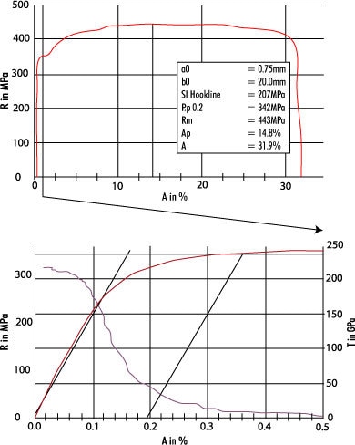
Figure 1. Characteristic stress/strain curve of a tensile specimen made of sheet steel (see above illustration) and enlargement of the section until shortly after the 0.2 %-proof stress with illustration of the local gradient T via “virtual” measuring channel (see below illustration)
Effect of Property Changes
When using tenacious materials, the (local) rigidity considerably decreases once having exceeded the yield stress and can even have values of zero or below (increasing deformation without force increase or even with a reduction in force).
The characteristic curve of a tensile specimen made of sheet steel (gauge length L0 = 80 mm) clearly proves the changing rigidity during increasing deformation. The mere elastic strain up to the yield stress is only approx. 0.06% (approx. 50 µm), the plastic strain up to the break is nearly 32 % (approx. 26 mm), i.e. more than the 500-fold! This behaviour makes particularly high demands on the deformation measuring systems which are to be used to determine the Young’s modulus of elasticity, proof stress, strain at maximum force and strain at break in the same test (i.e. high resolution and long test travels).
Moreover, the measuring system must not be damaged either during a sudden specimen break. Under the influence of the test force, not only the specimen is deformed, but there is also an elastic deformation of all testing machine components (load frame, load cell, specimen mountings and specimen parts outside the gauge length) located in the flux of force. Due to the large rigidity of the specimens, the elastic deformation of the testing machine is mostly clearly higher than the deformation of the specimen (up to more than the tenfold).
Young’s Modulus
For the measurement of these small deformations, e.g. for the determination of the Young’s modulus of elasticity and the proof stress, the indirect measurement via crosshead or piston travel is therefore practically impossible.
The crosshead or piston travel of the testing machine is according to the ratio between specimen and machine rigidity classified into specimen and machine deformation.
Therefore, the deformation speed does not only depend on the crosshead and piston speed, but also on the specimen dimensions (rigidity, geometry) and the machine configuration. But the deformation speed influences the characteristic values to be determined, in particular less rigid materials.
Therefore a comparability of the test results of specimens of different dimensions and of different machines can only be guaranteed if the crosshead or piston speed can be controlled based on the measured values of force and deformation.
Test Standards – Prerequisite for Comparable Results
One of the main tasks of the test standards is to create the same conditions for specimen and test sequence regardless of time and place of testing and of the tester. The international standards replacing more and more the national standards are an important step to further improve the comparability of test results.
The most important national and international standards applied today for the testing of metals are summarized in the following tables. In general, the standards are verified and adapted every five years provided the corresponding requests are available and a majority of the Standards Committees is given. Employees of Zwick Roell are active in several Standards Committees. Thus, they contribute their knowhow and experience of the manufacturer of testing machines and they are informed about the product development and the professional consulting of the customers.
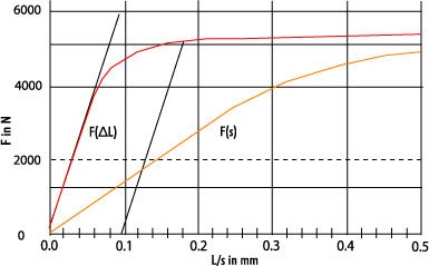
Figure 2. Characteristic force/extension/crosshead travel curve of a tensile specimen made of sheet steel (tested with a Zwick Z100 materials testing machine with hydraulic specimen grips)

This information has been sourced, reviewed and adapted from materials provided by ZwickRoell GmbH Co. KG.
For more information on this source, please visit ZwickRoell GmbH Co. KG
.