|
Information on mechanical properties of plastics such as tensile, flexural, compressive and shear that can help optimize material formulations, processes, and quality control, can all be derived from a universal testing machine. Advances in electronics and data acquisition and analysis software have improved their performance, ease-of-use, and even have led to more attractive pricing.
Universal Testing Machines
Universal testing machines (UTMs) that test mechanical properties such as tensile, flexural, compressive and shear are among the most commonly used instruments plastics compounders are likely to buy when outfitting a lab. Product development is among the key reasons compounders and resin makers test compounds and resins with UTMs. Others include testing the material to determine its suitability for various plastics processes and whether its properties will meet the particular end-use application, as well as for quality control following development to ensure lot-to-lot consistency. Traditionally, most plastics molders and extruders have relied on getting this information from their material suppliers. However, increased interest in improving quality control either of incoming material, or, more importantly, at the end of the manufacturing process, as well as product and process development, has led many processors to consider a UTM when outfitting or upgrading a lab.
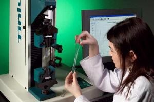
Figure 1. Plastic tensile specimen about to be tested in single column tensile
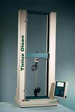
Figure 2. Twin column tensile tester, with a maximum load capacity of 2,200 lbf (10kN), shown testing some plastics strapping material.
The Various Tests a Universal Testing Machine can Perform
Universal testing machines allow you to stretch (tensile), bend (flexural), squash (compression) or pull (shear) a sample until it breaks.
The mechanical strength property can be classified, first in terms of the direction in which strain is induced in a specimen when a force is applied to it, and second, in terms of the speed at which the force is applied. Such static tests, commonly performed on plastics with a typical electromechanical universal testing machine, involve loading the specimen generally at speeds ranging from 0.001 to 20-in per min. (In contrast, dynamic or cyclic tests, such as fatigue, typically performed on servo-hydraulic UTMs, involve reduced loading over long periods of times.)
Electromechanical Universal Testing Machines
A typical electromechanical UTM repeats a test under the same controlled conditions on test samples, whether it’s pushing, pulling, bending, or squashing the sample; the only variable should be the material. You are looking to determine the material’s mechanical properties. Just as the speed of a test should be controlled, so should the shape of the sample. Most tensile specimens are designed to have the center section narrower than the ends, and thus commonly called “dogbone” specimens.
Data Acquisition in Modern Universal Testing Machines
Measurements of applied force (load) and deformation of the specimen are generally not made directly on the specimen. Instead, electrical signals are sent to a recorder device, typically a computer running data acquisition and analysis software. Of course, the earlier UTM machines that were analog with a chart recorder have been virtually replaced by digital controls and PC-driven software. The typical load/deformation curves represent two components-force on the Y-axis versus deformation on the X-axis. By far the most common tests performed on plastics with a UTM are tensile strength and modulus and flexural strength and modulus. All testing is done in accordance with specific ASTM and /or ISO standards. Testing in accordance with OEM standards, particularly in the automotive, aerospace and medical device arenas, may also be required.
Tensile Testing
Tensile testing is performed in accordance with ASTM D-638 as well as ISO 527 combined tensile and flexural procedure. Tensile properties are the most important single indication of strength in a material. The force needed to pull the specimen apart is determined, along with how much the material stretches before it breaks. The tensile modulus is the ratio of stress to strain below the proportional limit of the material. This is the most useful tensile data as parts should be designed to accommodate stresses to a degree well below it.
Toughness of a Material
While a high ultimate elongation may be an asset in applications where almost rubbery elasticity is desirable, for rigid parts there is little benefit that they can be stretched extremely long. However, moderate elongation is beneficial as it permits absorbing rapid impact and shock. As a result, the total area under a stress-strain curve is indicative of overall toughness and a measure of the amount of energy required to break the specimen.
Flexural Testing
Flexural testing is performed according to ASTM D790 and ISO 178. Flexural properties for plastics are derived by placing a specimen on two supports and applying the load at the center at a specified rate and the loading at failure is the flexural strength. In bending, the beam is subject to both tensile and compressive stresses. Because most thermoplastics do not break in this test, the flexural strength cannot be calculated. Instead, flexural stress at 5% strain is calculated-the loading needed to stretch the outer surface 5%.
Compression Testing
Less common are compression tests, although they play a major role in testing of rigid cellular plastic foams, which are tested in accordance with ASTM D1621 and ISO 844. The compressive strength of a material is calculated as the stress required to rupture the specimen or deform the specimen to a given percentage of its height. With the exception of foams, the compressive strength of rigid plastics is of limited design value, since they seldom fail from compressive loading alone. Still, compressive strength data may be useful in specifications for distinguishing between different grades of a material and, assessing the overall strength of different kinds of materials along with other data. Such tests are performed according to ASTM D695 and ISO 604.
Shear Tests
Shear tests are rarer for most plastics, according to suppliers of UTMs. Shear strength is obtained by placing a specimen in a punch type shear fixture and the punch is pushed down at a rate of 0.005/min, until the moving portion of the specimen clears the stationary portion. Shear strength is calculated as the force/area sheared. It is important in film and sheet products where failures from this type of load can occur, whereas for the design of molded and extruded products it is rarely a factor. Plastic sheets or molded plastic discs measuring 0.005 to 0.500 in. thick are used in the test according to ASTM D732 (no ISO equivalent).
Grips and Fixtures
How a sample is held on the base of the machine is key since the type of test that is performed is determined by the type of grip or fixture used. There are hundreds of different grips and fixtures differing in mechanical design for specimen material and design. For tensile testing of plastics, the most common type is the wedge-action, self-tightening grip-it self tightens as load is increased. For flexural tests, the most common is the three-point bend fixture. Compression platens are used for compression testing; these are saucer-shaped with a precision grade surface that attaches to the machine's load cell.
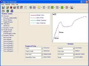
Figure 3. Screenshot from test set-up section of QMat software showing available results selection.
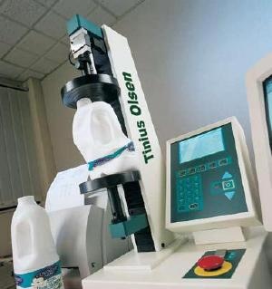
Figure 4. Single column low force tester testing the compressive strength of plastic milk containers.
Configuration of Universal Testing Machines
A UTM consists of one or two vertical load bearing columns on which are mounted a fixed base horizontal plate and a moveable horizontal crosshead on top. In today’s UTMs the columns are usually of a ball screw drive construction to position the moveable crosshead, allowing the workspace to remain between the machine base and the moving crosshead.
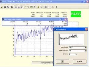
Figure 5. Resultant graph generated by PC based QMat software, showing the result of a peel test.
Load Cells and Load Ratings
The size of a UTM is described by a combination of the maximum load rating of the frame and the load cell or load sensor device that measures the load/force. The load cell is attached to the moving crosshead that is driven by electric motors. A load cell in series with the grip measures the force, which can be displayed on a digital display or a PC. Depending on the design, the load cell can be replaced with another load cell that is better matched to the material under test, within the maximum limits of the tensile tester’s supporting frame.
Load Capacities and Configurations for Testing of Plastics
The commonly used electromechanical units range in capacity from 100 to 135,000 lbs. Whether single- or dual-column, the most commonly used machines in testing plastics are vertical benchtop units. The same principles apply to horizontal machines which are primarily relegated for use in automated processes that utilize robots to continuously test samples. Single-column UTM machines are lower force machines and lower cost. They come in frame capacities up to 1000 lbf. Dual-column UTMs are available in load frame capacities from 1000 to 15,000 lbf (they are available at higher capacities but are extremely unlikely to be used for testing plastic specimens). UTMs can be outfitted with interchangeable load cells They are typically available from as little as 1lb capacity and will range up the machine’s maximum capacity. (E.g., a 100-lb load cell placed in a 1000 lb frame unit allows for measuring up to 100 lb at +- 0.5% accuracy.)
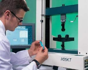
Figure 6. Flexural test on a reinforced plastic specimen.
Choosing A Single-or Dual-Column Configuration
How much maximum load you will typically need based on the type of materials you are testing is among the key issues to consider in deciding whether to opt for a single-column or a dual-column machine.
Controlled Environment Testing
Also consider whether you will require a large environmental (thermal) chamber for temperature resistance testing. The dual units are taller machines that allow for larger samples to be placed in larger thermal cabinets that are inserted between the columns.
Machine Stiffness
How stiff you want the frame to be is another consideration. Dual-column machines are stiffer by nature of their design and as a result there is less deflection during testing. Also, if you will be doing any compression testing of foams, a dual-column unit is typically required as the sample is larger. Other issues include your space availability, and the amount of crosshead travel that will be required.
Computer Driven Machines Reduce Costs
Last, but not least, is the cost issue. The newest PC-driven UTMs are less expensive than the digital control panel machines that have been around for more than a decade as they have simpler electronic controls and often do away with the digital display that provide the graphical readout.
Introduction to Tensile, Compression, Tear, Peel and Flexure Testing
No introduction to tensile / compression/ tear / peel / flexure etc. testing would be complete without a small bit of theory. A lot of it is common sense, but there are some technical, and industry specific, terms that need to be addressed:
Load
This is the amount of force that is applied to the specimen, as measured by the loadcell in the testing machine, and is expressed in either lbf, kgf or N (pounds of force, kilograms of force or Newtons)
Extension
This is the amount of travel that is required to apply the load and is measured in inches or mm
Stress
This is the amount force applied divided by the cross-sectional area. Typically, the cross-sectional area of the specimen that is used is the original cross section of the gauge length area of the specimen, and this is commonly referred to as the engineering stress. In some labs and applications, true stress is used; this is the load divided by the actual cross-sectional area; as the test proceeds, test specimens typically thin out, or neck, as the test proceeds so true stress becomes very difficult to measure since the cross sectional area is changing. Stress is measured in psi or MPa (pounds per square inch or megapascals).
Strain
Strain is measured as the change in length of the gage length divided by the original gage length. Since this is really a ratio, strain is measured in %.
Hooke's Law
Almost every material obeys Hooke's Law, which states that if a load is applied to a material, it will deform in a proportional manner to the amount of applied load. While its true that most materials obey Hooke's Law, they only obey this up to the limit of proportionality.
Modulus of Elasticity
The modulus of elasticity is simply the ratio of stress to corresponding strain below the proportional limit of the specimen. Put another way, it is the slope of the stress vs strain graph in the elastic region of the test. This is also referred to as Youngs modulus; since it is calculated as the stress divided by the strain, it has units of psi or N/mm2
Yield Point
This is the point at which it is considered that the proprtional limit and behaviour has stopped and the material has entered into the 'plastic' zone. It is recognised by convention, as the point where there is an increase in strain without a corresponding increase in stress.
Ultimate Point
This is the point at which the maximum stress the specimen and material is capable of withstanding is reached.
Breaking Point
This is the point at which the sample finally breaks. It should be noted that the Breaking point and the Ultimate point are, more often than not, two separate, distinct points on the stress / strain graph.
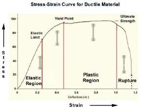
Figure 7. Stress-strain curve for ductile material
|