Oct 26 2012
Topics Covered
Introduction
High Temperature or Type I Hot Corrosion
Low-Temperature or Type II Hot Corrosion
Summary
About ASM International
Introduction
Various test methods have been used to study hot corrosion. Immersion testing (or crucible testing), which was the first laboratory test method, is not considered reliable for simulating the gas turbine environment. The salt-coated method is quite popular in academia for studying corrosion mechanisms. Engine manufacturers, however, use the burner rig test system to determine relative alloy performance ranking. The rig burns fuel with excess air to produce combustion gases with continuous injection of a synthetic sea-salt solution. This type of test system represents the best laboratory apparatus for simulating the gas turbine environment. A special issue of High Temperature Technology published in 1989 contained a number of papers discussing burner rig test procedures. The data reviewed here are limited to those generated by burner rig test systems.
 |
| Created from content provided by ASM International in the book “Metallurgy for the Non-Metallurgist, Second Edition” Editor(s): Arthur C. Reardon |
High Temperature or Type I Hot Corrosion
Bergman et al. studied hot corrosion resistance of various nickel- and cobalt-base alloys at temperatures from 870 to 1040 °C (1600 to 1900 °F) with 5 ppm sea-salt injection. Their results are tabulated in Table 1. The data show a good correlation between alloy performance and chromium content. Increasing chromium in the alloy significantly improves resistance to hot corrosion. Alloys with 15% Cr or less are very susceptible to hot corrosion attack. Cobalt- base alloys are generally better than nickel-base alloys. This may simply be due to higher chromium contents in cobalt-base alloys. One nickel-base alloy (Hastelloy X) with a chromium level similar to those of cobalt-base alloys was found to behave similarly to cobaltbase alloys.
Table 1. Results of burner rig hot corrosion tests on nickel- and cobalt-base alloys
| Alloy |
Chromium content in alloy, % |
Loss in sample diameter, mm (mils) |
| 870 °C (1600 °F) 500 h |
950 °C (1750 °F) 1000 h |
980 °C (1800 °F) 1000 h |
1040 °C (1900 °F) 1000 h |
| SM-200 |
9.0 |
1.6 (64.4) |
3.3+ (130+) |
… |
… |
| IN100 |
10.0 |
3.3+ (130+) |
3.3+ (130+) |
… |
… |
| SEL-15 |
11.0 |
3.3+ (130+) |
3.3+ (130+) |
… |
… |
| IN713 |
13.0 |
3.3+ (130+) |
2.0+ (77+) |
… |
… |
| U-700 |
14.8 |
1.7+ (66+) |
1.6 (63.9) |
… |
… |
| SEL |
15.0 |
1.2 (45.8) |
1.3 (51.8) |
0.3 (11.4) |
… |
| U-500 |
18.5 |
0.2 (7.6) |
0.8 (31.7) |
0.7 (29.3) |
… |
| Rene 41 |
19.0 |
0.3 (10.3) |
… |
0.8 (30.8) |
… |
| Hastelloy alloy X |
22.0 |
… |
0.3 (12.0) |
0.4 (15.2) |
… |
| L-605 (alloy 25) |
20.0 |
… |
0.4 (15.3) |
0.3 (11.3) |
1.1 (41.9) |
| WI-52 |
21.0 |
0.5 (21.4) |
0.5 (18.2) |
… |
1.9 (73.9) |
| MM-509 |
21.5 |
… |
0.3 (10.9) |
… |
0.8 (31.8) |
| SM-302 |
21.5 |
0.14 (5.4) |
0.3 (10.0) |
… |
0.6 (23.1) |
| X-40 |
25.0 |
0.11 (4.2) |
0.3 (11.6) |
… |
0.5 (18.5) |
Note: 5 ppm sea salt injection.
Among the alloys tested, alloy X-40 (Co-25Cr-10Ni-7.5W) performed best. This is in good agreement with the operating experience obtained by Royal Navy Ship (U.K.), which has demonstrated the superior hot corrosion resistance of alloy X-40 in a marine environment. Alloy X-40 was also found to be significantly better than nickel-base alloys, such as B-1900, U-700, U-500, and IN738 (Table 2). After 240 h, alloy X-40 showed hardly any corrosion attack, while alloy B-1900 (Ni-10Co-8Cr-6Mo-4.3Ta-6Al-1Ti) suffered severe attack. Alloy U-500 (Ni-18Co-19Cr- 4Mo-2.9Al-2.9Ti) and IN738 (Ni-8.5Co-16Cr- 1.7Mo-2.6W- 1.7Ta-0.9Nb-3.4Al-3.4Ti) were similar, suffering only mild attack. Surprisingly, alloy U-700 (15% Cr) was found to be slightly worse than alloy B-1900 (8% Cr). Alloy B-1900 along with IN100 (10% Cr) and Nimonic 100 (11% Cr) were considered to be poor in hot corrosion and suggested that they not be considered for use without coatings, even in mildly corrosive environments.
Table 2. Results of burner rig tests at 874 °C (1605 °F) for nickel- and cobalt-base alloys
| Exposure time, h |
Penetration depth, mm/1000 h (mils/1000 h) |
| B-1900 |
U-700 |
U-500 |
IN738 |
X-40 |
| 100 |
2.8 (111) |
… |
… |
… |
… |
| 170 |
2.5 (97) |
3.3 (129) |
0.7 (29) |
… |
… |
| 240 |
2.1 (83) |
… |
0.5 (20) |
0.9 (35) |
Slight |
Note: Diesel fuel containing 1.0% S, 125 ppm Na, 15 ppm Mg, 4.8 ppm Ca, 4.1 ppm K, and 225 ppm Cl, air-to-fuel ratio was 50 : 1, and 100 h cycle.
Burner rig tests were conducted using residual oil, containing 3% S and 325 ppm NaCl (equivalent to 5 ppm NaCl in air), at 870 °C (1600 °F) for 600 h on several cobaltbase alloys, which were X-45 (Co-25Cr-10Ni-7.5W), MAR-M302 (Co-21.5Cr-10W-9Ta-0.2Zr), MAR-M509 (Co-21.5Cr-10Ni-7W-3.5Ta-0.2T-0.5Zr), S-816 (Co-20Cr-20Ni-4W-4Nb-4Mo), FSX-418 (Co-30Cr-10Ni-7W-0.15Y), and FSX-414 (Co-30Cr-10Ni-7W). The test results are shown in Fig 1. All six cobalt-base alloys with chromium varying from 20 to 30% suffered little corrosion attack (about 0.04 to 0.12 mm, or 0.002 to 0.005 in., or 2 to 5 mils). Under the same test condition, Udimet 700 (Ni-15Cr- 18.5Co-5.2Mo-5.3Al-3.5T) suffered about 0.76 mm (0.03 in., or 30 mils) of attack. Figure 2 summarizes the data for a group of nickel- and cobalt-base alloys at 870 to 1040 °C (1600 to 1900 °F). Alloy U-700 was found to be inferior to IN713 at 950 °C (1750 °F). This was contrary to field experience. Alloy U-700 has served most reliably in aircraft jet engines, whereas IN713 has suffered severe hot corrosion in many applications. The authors attributed the high corrosion rate of alloy U-700 to the low chromium content in this heat (i.e., 13.6% versus 15.0% for regular heats).
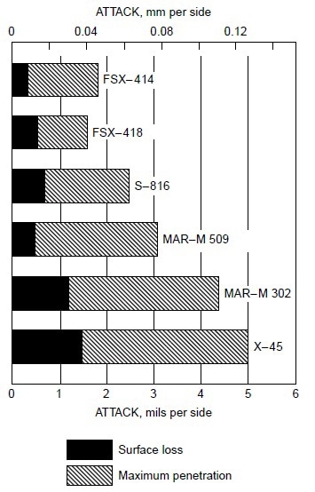
Figure 1. Relative hot corrosion resistance of cobalt-base alloys obtained from burner rig tests using 3% S residual oil and 325 ppm NaCl in fuel (equivalent to 5 ppm NaCl in air) at 870 °C (1600 °F) for 600 h.
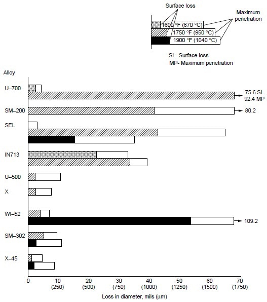
Figure 2. Relative hot corrosion resistance of nickel- and cobalt-base alloys obtained from burner rig tests at 870, 950, and 1040 °C (1600, 1750, and 1900 °F) for 100 h, using 1% S diesel fuel, 30:1 air-to-fuel ratio, and 200 ppm sea-salt injection.
A systematic study was conducted to determine the effects of alloying elements on hot corrosion resistance. In the Ni-10Co-15Cr-4Al-2Ti system, decreasing chromium from 25 to 10% resulted in increases in hot corrosion attack (Fig. 3). The data also suggest that decreasing aluminum while increasing titanium improves hot corrosion resistance. Furthermore, addition of 8% W to Ni-10Co-15Cr-4Al-2Ti alloy resulted in no apparent change in hot corrosion resistance. In binary and ternary alloy systems of nickel- and cobalt-base alloys, these authors further observed the effectiveness of chromium in improving hot corrosion resistance at 910, 950, and 1040 °C (1675, 1750, and1900 °F). Results are shown in Fig. 4.
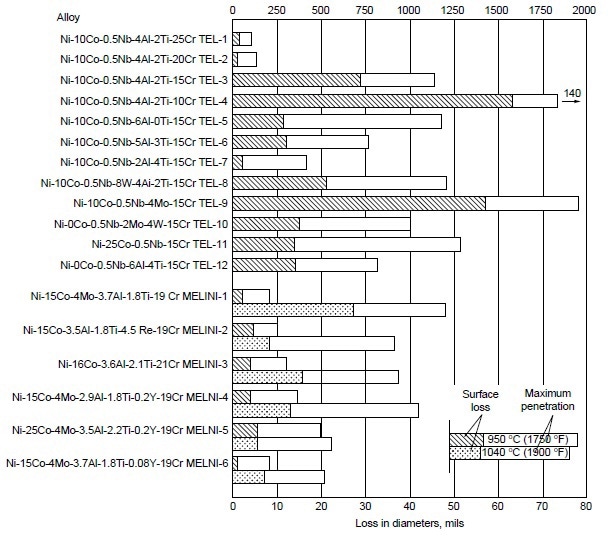
Figure 3. Relative hot corrosion resistance of experimental alloys obtained from burner rig tests at 950 and 1040 °C (1750 and 1900 °F) for 100 h, using 1% S diesel fuel, 30:1 air-to-fuel ratio, and 200 ppm sea-salt injection.
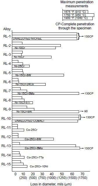
Figure 4. Relative hot corrosion resistance of experimental alloys obtained from burner rig tests at 910, 950, and 1040 °C (1675, 1750, and 1900 °F) for 100 h, using 1% S diesel fuel, 30:1 air-to-fuel ratio, and 200 ppm sea salt injection.
In examining the effect of the third alloying element in Ni-Cr alloys, they found that:
- Tungsten (8%) showed little effect at 910 and 950 °C (1675 and 1750 °F), but a slightly detrimental effect at 1040 °C (1900 °F).
- Cobalt was only slightly beneficial.
- Molybdenum was detrimental at 1040 °C (1900 °F), but had little effect at lower temperatures.
- Titanium (5%) showed significant improvement at 1040 °C (1900 °F), but little effect at lower temperatures.
- Aluminum (8%) was detrimental, causing severe hot corrosion attack at 1040 °C (1900 °F).
For Co-25Cr alloys, the effect of the third alloying element was summarized as:
- Tungsten (8%) was detrimental at 1040 °C (1900 °F), with little effect at lower temperatures.
- Molybdenum (6%) was detrimental at 950 and 1040 °C (1750 and 1900 °F), with little effect at 910 °C (1675 °F).
- Tantalum (7%) and nickel (10%) showed little effect.
Burner rig tests were conducted at 900 °C (1650 °F) on several wrought superalloys and nickel aluminides. The combustion gas stream was generated by using No. 2 fuel oil containing about 0.4 wt% S with an air-to-fuel ratio of 35 to 1 and injection of either 5 or 50 ppm sea salt into the combustion gas stream. The specimens were loaded in a carousel, that rotated at 30 rpm during testing to ensure that all the specimens were subjected to the same test condition. The specimens were cycled out of the combustion gas stream once every hour for 2 min, during which time the specimens were cooled by forced air (fan cool) to less than 205 °C (400 °F). Superalloys tested were alloy X (Ni-22Cr-18.5Fe-9Mo-0.5W), alloy S (Ni-15.5Cr-14.5Mo-0.05La), alloy 230 (Ni-22Cr-14W-2Mo-0.02La), alloy 625 (Ni-21.5Cr-9Mo-3.6Nb), alloy 188 (Co-22Cr-22Ni-14W-0.04La), alloy 25 (Co-20Cr-10Ni-15W), and alloy 150 (Co-27Cr-18Fe). Two nickel aluminides, IC-50 (Ni-11.3Al-0.6Zr-0.02B) and IC-218 (Ni-7.8Cr-8.5Al-0.8Zr-0.02B), which were developed by Oak Ridge National Laboratory, were included in the test program.
The results of tests at 900 °C (1650 °F) for 200 h with 50 ppm sea salt are summarized in Table 3. Both IC-50 and IC-218 nickel aluminides suffered severe hot corrosion attack after 200 h at 900 °C (1650 °F) with 50 ppm sea salt being injected into the combustion gas stream. Scanning electron microscopy with energy-dispersive x-ray spectroscopy (SEM/EDX) analysis showed that both nickel aluminides exhibited porous nickel or nickel-rich oxides with nickel sulfide penetrating through the remaining metal. Figure 5 shows the cross section of a corroded IC-218 specimen after hot corrosion burner rig testing at 900 °C (1650 °F) for 200 h with 50 ppm sea salt, revealing the formation of nickel oxides and nickel sulfides. SEM/EDX analysis showed that a thin, protective chromium-rich oxide scale formed on alloys X, 230, and 188.
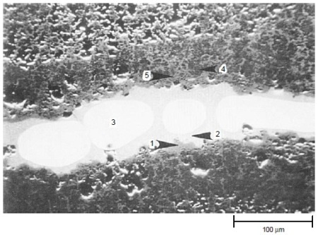
Figure 5. Scanning electron backscattered image showing the cross section of a corroded IC-218 nickel aluminide specimen after hot corrosion burner rig testing at 900 °C (1650 °F) for 200 h with 50 ppm sea salt using No. 2 fuel oil (0.4% S) for combustion at 35:1 air-to-fuel ratio. The results (wt%) of EDX analysis are: 1: 100% Ni; 2: 74% Ni, 26% S; 3: 100% Ni; 4: 88% Ni, 8% Cr, 4% Al; and 5: 98% Ni, 2% Al. Areas 1, 4, and 5 were essentially nickel oxides, area 2 was nickel sulfide, and area 3 was pure nickel. Courtesy of Haynes International, Inc.
Table 3. Results of burner rig hot corrosion tests at 900 °C (1650 °F) for 200 h with 50 ppm sea salt with specimens being cycled once every hour
| Alloy |
Weight change, mg/cm2 |
Metal loss, mm (mils) |
Total depth of attack(a), mm (mils) |
| X |
-0.76 |
0.02 (0.6) |
0.07 (2.8) |
| 230 |
-1.35 |
0.02 (0.8) |
0.06 (2.4) |
| 25 |
-1.62 |
0.02 (0.9) |
0.07 (2.8) |
| 188 |
0.93 |
0.02 (0.7) |
0.04 (1.6) |
| IC-50 |
72 |
>0.72 (28.3), completely corroded |
>0.72 (28.3), completely corroded |
| IC-218 |
83 |
>0.75 (29.5), completely corroded |
>0.75 (29.5), completely corroded |
(a) Metal loss + internal penetration.
Alloy 25, although exhibiting little weight change (Table 3), showed evidence of initial breakdown of the chromium-rich oxide scale. SEM/EDX analysis revealed the formation of cobalt-rich oxide nodules on the outer oxide scale on alloy 25. This indicated the initiation of the breakaway corrosion for alloy 25 after 200 h at 900 °C (1650 °F) with 50 ppm sea salt. Longterm test results under the same test condition clearly showed that alloy 25 suffered severe hot corrosion in excess of 200 h of testing, as shown in Fig. 6.
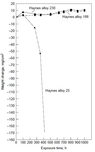
Figure 6. Results of burner rig tests at 900 °C (1650 °F) with 50 ppm sea salt using No. 2 fuel oil (0.4% S) for combustion at 35:1 air-to-fuel ratio for alloys 230, 188, and 25.
Figure 6 also shows alloys 230 and 188 exhibiting very little weight change for exposure time up to 1000 h. The results of the 1000 h tests are summarized in Table 4. Three nickel-base alloys (alloys S, X, and 625) and one cobalt-base alloy (alloy 25) were completely corroded before the test reached 1000 h, while nickel-base alloy 230 and cobalt-base alloys 150 and 188 exhibited little corrosion attack after 1000 h. Under the same test conditions in the same burner rig, nickel-base alloy HR-160 with 29% Co, 28% Cr and 2.75% Si was found to perform as well as alloys 230, 150, and 188. Figure 7 shows the conditions of the test specimens comparing HR-160 with other wrought alloys. Another burner rig test was conducted with 5 ppm sea salt at 900 °C (1650 °F) under the same combustion conditions (i.e., No. 2 fuel oil with 0.4% S and 35-to-1 airto-fuel ratio). The results are summarized in Table 5. Even at this low level of sea salt (5 ppm) in the combustion gas stream, cobaltbase alloy 25 continued to exhibit very poor hot corrosion resistance compared with some nickelbase alloys.
Table 4. Results of burner rig hot corrosion tests at 900 °C (1650 °F) for 1000 h with 50 ppm sea salt with specimens being cycled once every hour
| Alloy |
Weight change, mg/cm2 |
Total depth of attack(a), mm (mils) |
| S |
… |
Completely corroded in 350 h (1.3 mm, or 49.2 mil thick specimen) |
| X |
… |
Completely corroded in 500 h (1.2 mm, or 45.9 mil thick specimen) |
| 625 |
… |
Completely corroded in 940 h (1.6 mm, or 63.7 mil thick specimen) |
| 230 |
11.5 |
0.11 (4.4) |
| 25 |
… |
Completely corroded in 476 h (1.0 mm, or 37.8 mil thick specimen) |
| 150 |
10.0 |
0.13 (5.2) |
| 188 |
9.9 |
0.08 (3.2) |
Note: (a) Metal loss + internal penetration
Table 5. Results of burner rig hot corrosion tests at 900 °C (1650 °F) for 1000 h with 5 ppm sea salt with specimens being cycled once every hour
| Alloy |
Weight change, mg/cm2 |
Metal loss, mm (mils) |
Total depth of attack(a), mm (mils) |
| X |
-0.24 |
0.04 (1.6) |
0.14 (5.5) |
| 230 |
-0.79 |
0.03 (1.2) |
0.13 (5.1) |
| 625 |
5.87 |
0.05 (1.9) |
0.14 (5.3) |
| 25 |
… |
… |
Completely corroded (1.09 mm, or 43 mils) |
| 188 |
1.09 |
0.02 (0.8) |
0.07 (2.8) |
Note: (a) Metal loss + internal penetration.
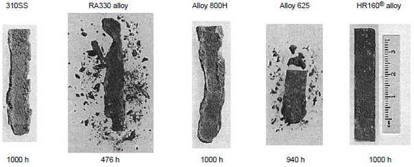
Figure 7. Test specimens alloy HR-160, 625, 800H, RA330, and Type 310 at 900 °C (1650 °F) in the combustion gas stream generated by a burner rig using No. 2 fuel oil (0.4% S) for combustion at 35:1 air-to-fuel ratio and with injection of 50 ppm sea salt into the combustion gas stream. During testing, specimens were cycled once every hour.
Low-Temperature or Type II Hot Corrosion
“Low-temperature” or Type II hot corrosion has been observed at temperatures lower than the temperature range where Type I hot corrosion has been encountered. Severe hot corrosion of alloy S590 and Nimonic 80A after several thousand hours of operation in a gas turbine that burned blast-furnace gas with the 700 to 730 °C (1290 to 1345 °F) turbine entry temperature was reported. In 1976, a new form of hot corrosion attack of gas turbine airfoil materials in a marine gas turbine was reported. The first-stage turbine blades coated with a CoCrAlY coating, which had exhibited satisfactory hot corrosion resistance for metal temperatures in the range 800 to 1000 °C (1470 to 1830 °F), were found to suffer corrosion attack for metal temperatures at about 600 to 730 °C (1110 to 1345 °F). The corrosion products formed on the CoCrAlY coating were found to contain CoSO4 and NiSO4. It was proposed that the mechanism of low-temperature hot corrosion attack of a CoCrAlY coating involved the formation of the low melting Na2SO4- CoSO4 eutectic (melting point of 565 °C, or 1045 °F). Nickel-base alloys were, in general, more resistant to Type II hot corrosion than cobalt- base alloys. It was also found that NiCrAlY and NiCoCrAlY coatings were, in general, more resistant than CoCrAlY coatings.
Increases in chromium content in superalloys and coatings provided significant increases in low-temperature hot corrosion resistance (750 °C, or 1380 °F) for these materials. Both IN939 (23% Cr) and NiCrAlY coating (39% Cr) were found to exhibit good low-temperature hot corrosion resistance. NiCrAlY coatings with 26, 34, and 42% Cr were tested and found significant resistance to low temperature hot corrosion for coatings with only 34 and 42% Cr. MCrAlY coatings (M = Co and/or Ni) with 30 to 35% Cr were tested. All of the coatings showed improved resistance to low-temperature hot corrosion (705 °C, or 1300 °F) compared with CoCrAlY coating with about 20% Cr. A critical chromium content of no less than 37% was required for cobalt-base coatings to provide resistance to both low- and high-temperature hot corrosion.
Summary
High-temperature or Type I hot corrosion generally occurs in the temperature range of 800 to 950 °C (1470 to 1740 °F). It is believed that the molten sodium sulfate deposit is required to initiate hot corrosion attack. The Type I hot corrosion morphology is typically characterized by a thick, porous layer of oxides with the underlying alloy matrix depleted in chromium, followed by internal chromium-rich sulfides. Low-temperature or Type II hot corrosion generally occurs in the temperature range of 670 to 750 °C (1238 to 1382 °F). Type II hot corrosion is characterized by pitting attack with little or no internal attack underneath the pit. Cobalt-base alloys are more susceptible to Type II hot corrosion, which generally involves Na2SO4 and CoSO4. Increasing chromium in alloys or coatings will improve the resistance of the material to both Type I and Type II hot corrosion attack.
About ASM International
Professional society for materials engineers. Develops and distributes technical information through electronic media, publications, conferences.

This Article was created from Material provided by ASM International in the book "Metallurgy for the Non-Metallurgist, Second Edition" Edited by A.C. Reardon.
For More information please contact ASM International.