Optically efficient and made to an ultra-high-grade, Process Insights’ durable fiber optic cable combines the best materials available in jacketing, coatings, cladding and core purity. Even though this fiber optic cable is incredibly durable, a proper handling technique is essential to mitigate cable damage during installation. This article should be used as a guideline in order to ensure the best performance from Process Insights fiber optic cables upon installation.
Cable Installation and Pulling
In order to install cable into the conduit and cable trays, hand pulling is permitted for short distances. The cable itself is quite stiff, so it can even be pushed from the reel into the conduit. If the conduit is fully clean it is possible to install 10 to 20 meters of cable in this way. Kinking and looping of the cable should be avoided at all costs and the cable should also not be forced at any point.
Although hand pulling cable is permitted, the most widely used installation practice is to use a cable pull tool. When using a cable pull tool the cable should be secured with a cable pull that will pull on more than 4 inches of the cable jacket only. The connector should not be pulled at any point.
Where the cable terminates, the vinyl protector should be left in place and a wrapping tape such as electrical tape should be used around the body of the connector to leave a smooth end. Another way to secure terminated cable is through the use of a wooden boat which is shaped to seat the connector, with an attached stringer on the front end of the wooden boat, and a cable-puller fastened to the rear of the boat. A small amount of travel should be allowed within the boat (several centimeters) for the connector.
The end goal of each of these pulling methods is to evenly distribute tensile forces on the cable jackets; away from the connector. The overall tensile force should have an upper limit of 50kg. The bend radii on both the conduit and the cable should not be smaller than 15 cm. Any sharp edges and corners are to be avoided in cable trays and conduit.
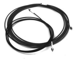
Process Insights Fiber Optic Cable with Connectors
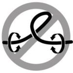
Warning! Do Not Kink the Glass Fiber Optic Cable
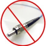
Warning! Do not pull on the Connector.
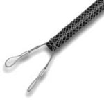
Warning! Only pull cable by hand short distances. Use a cable-pull tool to avoid damage to the fiber.
Dereeling
Once the cable is wound on to the reel, the cable develops a ‘set’. This has a radial and torsional component. After the cable is taken off of the reel (dereeled) it can form loops and the end of the cable may rotate about its axis if the removal process is different for the winding process.
Best practice to dereel the cable is to pull the cable from the reel whilst the reel is rotated. When dereeling a long cable it is best to use a friction clutch (5-10 kg, 10-20 lbs) which is used with a spindle through the reel hub in order to rotate it.
Installation Guidelines for Fiber and Probe
- It is recommended that the optical fiber should run through a conduit or cable tray. This provides mechanical and environmental protection for the fiber.
- A flexible and watertight conduit can be used to connect the probe to the rigid conduit. When doing this there must be enough slack left in the flexible conduit so that there is enough give for the probe during cleaning, referencing or removal from the process line.
- If the fiber is to be run unprotected, it is necessary for a protective sleeve or coupling to be installed on the probe to protect the bulkhead/SMA connector from the elements.
- Junction boxes that will hold extra fiber (using a standard 500”m core diameter) must all be at least 30 cm across. Fiber should never be subject to a bend radius of less than 15 cm, but a smaller radius may be acceptable for fiber which has a smaller core diameter.
- As probes require servicing periodically, the fiber cable must have adequate service loop in to facilitate servicing without removing the cable from the probe.
- Runs of fiber cable should be sized such that there is an extra 1 to 2 meters on each end. This will allow for servicing. Any extra fiber can be stored in the junction boxes.
- If the fiber connectors are not in use, they should be covered by the dust caps provided. Do not remove the caps until the fiber is fully installed.
- There must be adequate clearance to pull terminated cable through the conduit, so the conduit must be sized appropriately.
- The fiber cables are an essential part of the spectrometer, so terminations must be thoroughly inspected. If there are any flaws it will degrade the performance of the system. Therefore, Process Insights recommends that any fiber you purchase should be pre-terminated.
Free Standing Cables
If a cable is attached along the walls of a building, or along piping, it should be secured every 1 to 2 meters in both vertical and horizontal installations. When using cable ties to secure the cable it should be buffered from direct contact by a soft elastomer grommet, or it can be laid through a split soft tube of diameter 8 – 10 mm and length of 50 – 75 mm.
A cable drop of 15 – 20 cm per 1 – 2 m horizontal support will provide the best buffering. A guide wire should be used for aerial installations for support.
Please Note
Although this cable can support itself over 100 m or more, it will be overly sensitive to environmental effects. When attaching a guide wire, the process is the same as free standing cable but a soft adhesive, such as RTV silicone, is used in order to stop the drop of the cable from shifting in between two tie points.
Relaxation of the Cable
After the cable is installed it must be checked to look for crimping, sharp bends or loops. The cable will need time to relax once the installation is finished, this will take around 1-2 days at 25 °C but more time should be allowed if the ambient temperature is lower than this.
Effects of the External Environment on the Cable
Performance is influenced by the environment the cable is in. Low temperatures can affect the relative throughput of the cable, especially when the temperature is below -60 °C, as this can cause a phase change of the buffer material,
A slight effect on performance is caused by thin layering of ice on aerial installations. Permanent damage can occur from water freezing in underground ducts.
If the cable is used in a hydrogen-rich environment optical detail can be generated in the NIR spectral range. The hydrogen gas can permeate the glass filament which can cause spectral bands to appear. Hydrogen appears to be the only gas that causes this.
Understanding Jacketed Fiber Optic Cable
The single strand jacketed fiber optic cable from Process Insights has unique handling requirements due to the nature of the glass filament. The tensile strength of the glass filament is very high; however, it has a very low shear strength.
As a wave guide, the walls of the filament become sensitive to pressure, resulting in localized attenuation across broad spectral ranges and also in more narrow spectral ranges dependent on the periodicity of the pressure along the fiber axis.
The construction of the fiber optic cable is a glass fiber with a soft resilient material adjacent to the wave guide. This is followed by much harder materials. Longitudinal tensile members are used to off load tensile forces from the glass fiber.
Vibration
Vibration does not change the performance of the fiber optic cable unless the cable is under tension or compression longitudinally. If these conditions cannot be avoided, the cable should be shielded from contact which produces severe vibrations.

This information has been sourced, reviewed and adapted from materials provided by Process Insights – Optical Absorption Spectroscopy.
For more information on this source, please visit Process Insights – Optical Absorption Spectroscopy.