|
|
||||||
Railway Rails – Environmentally Assisted Sulphide Stress Corrosion Cracking in Railway Tracks |
||||||
Topics Covered |
||||||
|
Detection and Examination of Rail Associated Hardware Case Study – Rail Failure in an Underground Rail System Sulphide Stress Corrosion Cracking |
||||||
Background |
||||||
|
Today,
commuters in the UK face delays and sometimes derailments, as the rail
network continues to suffer from the problems of worn out and broken rails.
Heightened by the Hatfield train derailment in October 2000, the problem of
broken rails caused by mechanical failure has continued to hit the headlines
in recent years. Causes of Rail Failure
The
derailment at Hatfield was caused by gauge corner cracking. But this form of
mechanical failure is not the only failure mechanism of concern for railway
rails, particularly rails on underground systems that may suffer water
ingress. Corrosion, materials and environmental technology group CAPCIS
recently investigated a rail failure that was not the result of fatigue
cracking. After extensive testing, CAPCIS concluded that the rail had failed
due to sulphide stress corrosion cracking (SSCC) - a form of environmentally
assisted cracking. Detection and
Examination of Rail Associated Hardware
The
detection of cracks in rails usually involves the visual examination of the
rails, clips and base plates, and ultrasonic examinations of the railhead.
These inspections are focussed primarily on detecting fatigue cracks and rail
wear caused by the repeated contact with train wheels. Corrosion problems on
dc-powered traction systems are usually associated with stray currents. The
‘leakage’ of electrical current from its intended path can cause localised
corrosion of the rail or other equipment where the current leaves the
component. Case Study – Rail
Failure in an Underground Rail System
During a
project looking at stray current and other corrosion issues on an underground
dc traction system, CAPCIS was asked to investigate a somewhat unusual
failure of a rail. In-situ photographs of the fractured rail taken following
the incident suggested that the rail web had suffered severe thinning leading
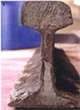
to overload failure. Initial Examination
However,
upon receipt of the rail sections and a cursory examination of the fracture
faces, it was clear that corrosion and thinning were not the direct cause of
the failure, figure 1.
Detailed Examination
Detailed examination of the fracture face revealed no obvious signs of fatigue cracking, and SEM examinations of the railhead and web showed only brittle fractures. In contrast to the railhead, the web and foot of the rail exhibited extensive corrosion, indicating that this was not a single event fracture. Magnetic Particle
Inspection
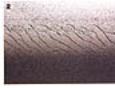
To check for the presence of any surface cracks the railhead was examined using magnetic particle inspection. A number of elongated S-shaped cracks were found running along the worn gauge corner of the rail, figure 2. These cracks, referred to as ‘head checking’, were typically 10mm in length, but there was no indication that the failure had originated at these surface cracks.
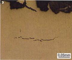
Metallurgical
Examination
However, further metallurgical examination of the web and
foot of the fractured rail revealed fine cracks typical of those caused by
hydrogen embrittlement of the steel, figure 3. The cracks ran mainly parallel
to the fracture faces and did not appear to be associated with any of the
small manganese sulphide inclusions running through the steel.
Hydrogen Testing
Hydrogen
levels in quality as‑manufactured steel are typically 1-2 ppm. The
chemical analysis of several sections from the web, foot and head of the rail
revealed elevated hydrogen levels in the steel far above those expected in
modern rail steel. Values of 2 ppm were recorded at the top of the web and
values of 5 ppm were found at the bottom of the web. The increased levels
were found to be the result of environmental hydrogen absorption. Environmental Inspection
During
inspections, it had been noted that while some areas of the tunnels were
apparently dry, others suffered water ingress in places. The tunnel
environment was also found to be damp and warm even though the ambient
temperature at street level was somewhat cooler. The source of the hydrogen
was finally traced to stagnant water pools beside and beneath the rails,
which were found covered with a white ‘scum’. When disturbed, hydrogen
sulphide gas (H2S) could be smelt immediately and lead acetate
paper turned brown, also indicating its presence. Chemical Testing
To
confirm the cause of the failure, azide tests (a chemical test carried out to
determine whether a material has been exposed to an environment containing
sulphides) were carried out on the rail, and a sample of the water was
returned to the laboratory for testing. A high level of sulphate-reducing
bacteria (104 SRB per ml) was found in the water. SRB are
micro-organisms that chemically reduce sulphate ions in the water to
sulphide. The corrosion reaction involving H2S produces monatomic hydrogen (H0) at
the corroding surface that should combine
to form H2 gas, but the presence of sulphide species retards or
poisons this combination reaction so that the hydrogen
diffuses into the steel. Positive azide tests and the presence of SRB led to
the conclusion that the rail almost certainly failed due to sulphide stress
corrosion cracking. Sulphide Stress
Corrosion Cracking
SSCC was first recognised in the 1950’s in the oil and gas industry and occurs in high strength steels at relatively low absorbed hydrogen levels. This form of cracking is highly dependent on the steel composition, microstructure, strength and total stress level (applied and residual) - the higher the strength of the steel, the greater the susceptibility to hydrogen embrittlement. The Path to Failure
The
presence of the hydrogen cracks explained the corroded regions on the
fracture face. Small cracks formed and grew with time to become surface
emergent, exposing the crack faces to the external environment allowing
further corrosion and hydrogen diffusion. The cracks eventually reached a
critical size such that the rail could not withstand the stresses induced by
the passage of trains and a brittle overload failure occurred. Sulphide Stress Corrosion Cracking and
its Elimination
While
this failure may not be unique it was unusual. CAPCIS has encountered many
SSCC failures in the oil and gas industry, but has never seen such a failure
in a section of rail. In the past, hydrogen-related failures of rails, such
as tache ovales, have been caused by fatigue cracking starting at small
hydrogen cracks in the railhead, but controlling hydrogen levels in the
as-made steel has largely eliminated these failures. Summary
While the detection of stray current corrosion and fatigue cracking of rails is fairly straight forward, the detection of SSCC would be extremely difficult for rail engineers. On-site azide tests are impractical and effective ultrasonic examination of a corroded rail web and foot would require extensive cleaning. Atmospheric H2S can be smelt, but the source is not always readily apparent. Add to this the fact that the detection of SRB requires a laboratory test and the diagnosis of SSCC is fraught with practical problems. The easiest way to minimise the risk of producing conditions conductive to SSCC is by controlling the tunnel environment and preventing water ingress and stagnation. |
||||||