Even the strongest and hardest-working materials on earth - pipes, drills, munitions, girders - crack. A crack is the beginning of failure, but when and how dramatically will the failure occur?
Increasing Material Demands
The world demands more-greater quantities of energy, taller buildings, longer pipelines, faster and higher-flying aircraft. Material scientists have responded with stronger and more durable metals, but every one, given the right set of circumstances, will crack.
We know more and demand more of materials than ever before. Rather than reacting to problems as they occur, more and more industries are choosing to be proactive in failure prevention by testing materials properties beyond the normal testing requirements. One such test that goes beyond traditional material property analysis is the CTOD test, which is gaining popularity in the oil and gas industry.
Crack Tip Opening Displacement CTOD
Crack Tip Opening Displacement test or CTOD is one of a family of fracture mechanics tests that measures the resistance of a material to growing a crack. Similar tests (i.e., da/DN, K1C, KEE, and J1C) can determine fracture resistance of a material, but CTODis particularly suited to pipeline and drilling equipment. The CTOD test is used to determine the fracture mechanics properties of ductile materials and can be thought of as the simulated opening of a pre-existing fatigue crack prior to fracture. The data that result from this opening can be used for critical defect assessment, in which the critical defect size can be determined.
The CTOD Test Process
Please note that the following is a simplified version of the CTOD test process and does not cover all aspects of the test, such as personalized testing specifications.
A CTOD test can be broken into 4 main steps:
1. Machining of the test specimen (Sample Machining);
2. Fatiguing of the specimen within specified limits (Pre-Cracking);
3. Breaking of the specimen under controlled conditions (Fracture);
4. Post analysis of the specimen and resultant data to obtain the CTOD value (Data Analysis).
Sample Machining for the CTOD Test
Unlike other destructive material tests, the CTOD test has multiple factors that can affect the resultant value. Not only is the test temperature a variable, but the specimen size can also affect the results, as well as the conditions in which the result can be used. It is important to use the maximum thickness of specimen possible when performing the test. As a general rule, if a material meets the TOD test requirements at a given test size, then the results can be extrapolated to apply to thinner sections, but not thicker.

Figure 1. Machining test samples for CTOD testing.
Commonly Used Test Specimens
For structural and pipe materials used in the oil and gas industries, the most commonly used specimens are a rectangular three-point bend or a square three-point bend. The rectangular three-point bend is preferable, except where there is limited material or a surface notch needs to be evaluated.
Testing Nomenclature for the CTOD Test
As with other destructive material tests, the CTOD value can vary, depending on the direction of the test. The various testing specifications have their own nomenclature to describe the sample and notch direction in respect to the grain flow or weld direction. This nomenclature is typically the same as that of a charpy test.
The Importance of the Pre-Fatigue Crack
The calculation of the final CTOD value is dependent on the depth of a pre-fatigue crack from the surface of the specimen. As it is impractical to fatigue a crack from the actual specimen surface, the specimen is machined to include a notch, which will act as the initiation point of the fatigue crack and be included in the overall length of the fatigue crack used for the calculation of the CTOD value.
National standards are used for the actual testing criteria.
Pre-Cracking
On completion of machining of the specimen, an actual fatigue crack is induced at the base of the starter notch. This crack must be of sufficient length to bypass any area of plastic deformation that may have been occurred during the machining process. The crack length is typically based on the size of the sample, the method of notch manufacture, the width of the notch, the shape of the notch, and practical time restraints. The overall length from the surface of the sample to the crack tip must fall within given parameters. Other factors that also must be considered include the angle of the crack in respect to the specimen and the difference in length of the crack as seen on the exposed surfaces. The operation is typically performed in air at room temperature.
Fatiguing the Sample
Fatiguing the sample requires a minimum and maximum fatigue load. If the loads selected to induce the fatigue crack are too low, then the fatigue time may become restrictive-or, at the extreme, a crack may not develop. If the loads are too high, then a plastic zone may result which would affect the CTOD result-or, again at the extreme, the sample may fracture prematurely. The national standards specify criteria to ensure a valid test sample, including: a minimum to maximum load ratio of less than 0.1, a change in stress intensity relating to the modulus of the material, and a maximum load based on the material tensile properties, specimen size and span used.
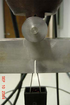
Figure 2. Fatiguing the CTOD test sample.
Initiation and Propagation of a Fatigue Crack
Initiation and propagation of a fatigue crack is dependent on the configuration of the sample, the crack length and the loading conditions. This relationship determines the stress intensity factor (K) at the fatigue crack tip, and can be determined for a three-point bend by the following formula:
[Where K is the stress intensity factor, F is the load, S the span, B the specimen thickness, W the specimen width and a the crack length].
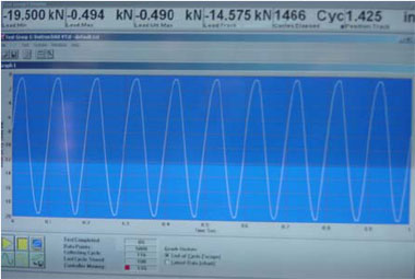
Figure 3. Fatigue loading of the CTOD test sample.
During the fatigue operation, W, B and S remain constant. The equation demonstrates a definitive relationship between the crack length, load and stress intensity.
Initiation and Growth of a Crack
To initiate and grow a fatigue crack for a CTOD test, various methods can be used.
a. Constant Load - A constant load amplitude (load) is the most common situation. However, for the purposes of growing a fatigue crack for a CTOD it is not the most practical. In order to meet the validity requirements imposed by the specifications, the load ratio selected would have to be determined based on the final crack length. As a result, the crack growth rate would increase as the length increased; however, it would be slow in the initial stages of crack length. This method can result in an extended time to grow the crack of the required length.
b. Decreasing Load - By calculating the load restrictions for a given crack length, it is possible to start the fatigue operation with a high load and decrease it to the limits required as the crack grows. Done carefully, this can save time in obtaining valid fatigue crack front, but it should be noted that reducing the load by too great an amount can result in the crack propagation slowing or even stopping. In this case, a given number of fatigue cycles would be needed to initiate the crack again.
c. Constant K - During the fatiguing of a CTOD sample, S, W and B will remain constant. As such, the relationship between the crack length, load and stress intensity can be utilized in the growth of a fatigue crack. From the equation it can be seen that by keeping the change in stress intensity constant, the load will drop proportionally as the crack length increases.
This method will result in an even load drop as the crack grows and will prevent the crack arrest that can occur when method b is used.
It is possible to combine aspects of the three methods to further increase to efficiencies of the crack propagation. By starting with a high K and reducing it as the crack extends, one can reduce the time necessary to grow a crack while keeping within the specification requirements.
Tracking Crack Length
Tracking the actual crack length can be done in a number of ways, such as:
a. Visual measurement can be made on the sample. Using this method, only the crack length at the outer surface can be determined. To enhance the crack, non-destructive testing techniques such as dye penetrant or magnetic permeability work well.
b. The compliance technique depends on a 5th order polynomial in which the coefficients are based on the specimen geometry and material properties. Typically, a clip gage is attached to the sample at the machined opening and electronically records the opening that is then related to the crack length. The recorded length can then be used to automatically adjust the load, based on the method decided for the crack growth, resulting in a smooth load drop.
c. The potential drop across the crack depends on ohm’s law: as a crack grows the potential will increase. As with the compliance technique, this method can be directly associated with the load control and hence give a smooth load transition.
Figure 4. Tracking crack length of CTOD test samples.
While performing the fatigue operation, it is important to remember that only the outer surface can be measured and confirmed. The fatigue is propagating across a plane inside the sample, and as such the length cannot be visually confirmed until the test is complete and the sample fractured open. The compliance and potential drop techniques can provide information about the internal situation of the fatigue crack.
Stress Distributions
Variance in length across the fatigue crack front increases in materials in which an even stress distribution is not present, i.e. in a weldment. In these cases, various operations may be necessary to produce a linear crack front. Precompression of the sides of the sample and reverse bending are two of the most common techniques employed.
Crack Front Examination
On completion of the fatigue operation, the visible crack front must be visually examined to ensure compliance to the specification, e.g. within length tolerances from the surface and between sides, straightness and the absence of any obvious surface bifurcations.

Figure 5. Examination of fracture surfaces can provide information about the type of failure that has taken place.
Fracture
The actual breaking of the specimen is performed under monotonic conditions, which means that the sample is under increasing load until fracture, and at a static temperature.
Maintaining Constant Temperature
Fractures can be affected by temperature, therefore it is important to control the temperature throughout the test. Testing in a liquid alcohol bath with CO2 as a cooling medium is one of the most common methods to achieve this.
Stress Intensity Factor
The rate of testing is determined by the change in the stress intensity factor during the initial application of load. As was seen in the equation, the stress intensity is dependent on the load and crack length. Since the crack length is not measurable until the sample is fractured, it is not possible to confirm the actual testing rate until completion of the test. An estimated crack length must be used to determine the testing rate-with the actual test rate confirmed to be with in the validation limits.
During the application of the load, a clip gage is used to measure the opening at the mouth of the fatigue crack. This opening is plotted against the load applied.
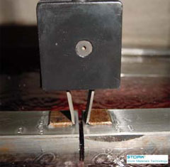
Figure 6. Use of a clip gage allows crack opening width to be measured.
Data Analysis
After the sample has been fractured, scientists perform various operations to determine the CTOD type and value.
The fracture face must be examined in conjunction with the plot of the load vs. the crack mouth opening. From this, the type of fracture can be determined.
CTOD Fracture Types
Three main categories of fracture exist:
a. m – in which the fracture face exhibits tearing and the final fracture occurs under decreasing load
b. u – in which the fracture face exhibits tearing and the final fracture occurs under increasing load
c. c – in which the fracture face does not exhibit tearing and the final fracture occurs under increasing load
Figure 7. The various modes of failure during CTOD testing.
Pop-in Failures
A 4th type of failure can occur which is known as a pop-in. In this situation, either a load drop, a displacement increase, or both is observed, and the load then recovers to exceed the initial condition. When a pop-in occurs, the material has partially fractured; however, the remaining ligand is sufficient to withstand the increase in load. It is often possible to see the cause of the pop-in on the fracture face. The validity of the pop-in is evaluated based on the changes in load and/or displacement. If deemed valid, the final calculation of the CTOD value is based on the load and displacement at the pop-in occurrence.
The length of the fatigue fracture and any tearing (in the case of a u type fracture only) should be measured. The fatigue crack length is used in the CTOD calculation.
Calculating CTOD Values
From the plot, the maximum load and the plastic component (Vp) of the crack opening is determined for use in the CTOD calculation.
The CTOD value is calculated from the following formula:

where ä is the CTOD, F is the load, S the span, B the specimen thickness, W the specimen width, a the crack length, v the poison’s ratio, Vp the plastic component corresponding to the load at the critical event, z is the clip gage height and óYS is the yield at test temperature.
The Final Result
When the graphical data has been analyzed, the sample measured and examined, and the CTOD value calculated, the validity of the result must also be evaluated.
As discussed above, some of the validity requirements of the CTOD test cannot be determined until the test is completed. A value may be obtained, there may be a minimum value of CTOD and/or type of fracture restrained, but, the test must also be valid. It is possible to have a result with a sufficient value to meet the specification requirement, but still have an invalid test. Similarly, your result may be lower than required with an invalid test. In these cases, the result obtained should not be used and the test should be repeated.
.png)
This information has been sourced, reviewed and adapted from materials provided by Element Materials Technology.
For more information on this source, please visit Element Materials Technology.