Introduction Many advanced materials, e. g., AlTiC (Al2O3-TiC composite), sapphire or SiC are used as a substrate for functional devices. Many of them are hard and difficult to machine. AlTiC has been used as a substrate of writing or reading head sliders for hard disc memory devices with a thin-film transducer element. A wafer of AlTiC of about 1.2 mm thickness was diced into chips (1 mm x 3 mm) by 70-300 μm thickness dicing blades. Conventionally, high feeding speeds (1-3 mm/s) and low edge chipping sizes (5-20 μm) are required for dicing of AlTiC chips [1]. In order to achieve these requirements, it is necessary to develop dicing blades by analyzing their grindability. Since commercial dicing equipments adopt a constant feeding-speed system, the force acting on a dicing blade alters during the dicing process due to the deterioration of their surface conditions, i. e., dislodgment or dullness of abrasive grains, deformations and abrasion of the matrix material. The altered forces make a dicing blade analysis complicated for a conventional dicing system. A constant feeding-force system, which enables to analyze the grindability of a grinding wheel, has been developed by our group [2-4]. Under constant feeding-force system, the feeding speed alters during processing, which depends on the surface conditions of a grinding wheel, and indicates its grindability. Recently, a constant feeding-force dicing system has been developed to analyze the grindability of dicing blades [5, 6]. In this study, the theoretical grindability of dicing blades was estimated by establishing a new model for feeding speeds under constant feeding-force dicing systems. The model was evaluated by comparing empirical and theoretical dicing speeds for different abrasive grain sizes. Experimental Three kinds of dicing blades were fabricated with different diamond grain sizes, 5-12 μm (#1200), 10-20 μm (#800), and 30-40 μm (#500). WC-Co was used as a matrix material [5,6]. The dicing blades consisted of 31 vol% of pores, 38 vol% of diamond grains, and 31 vol% of WC-Co matrix material. Their thickness was between 85 and 90 μm. The fabricated dicing blades were dressed under wet condition by using a plate containing alumina abrasive grains of mesh number 600. The dressing conditions were 2.0 mm dicing depth, 1 mm/s feeding table speed and 240 mm dressing length. The number of grains and the distribution of grains on the surface of all fabricated dicing blades were observed by using a confocal laser microscope (CLM). After dressed, dicing tests were conducted under 2.0 N of a constant feeding-force with cooling water. A constant feeding-force system is schematically shown in Figure 1. A linear slider was installed on a worktable of a commercial dicing machine to transmit constant force to a cutting specimen. AlTiC wafers with 1.2 mm thickness were cut into a plate of 75 mm length and 70 mm width. The AlTiC plate was placed on a zirconia plate with grooves of 1.0 mm width and 3.0 mm depth in the dicing direction. The grooves were located to avoid contact of the blades with the zirconia sample holder. Processing periods of different lines were measured during dicing tests. Feeding speeds for different lines were calculated from the length of cut sample divided by the processing period. 
Figure 1. Schematic illustration of the constant feeding-force dicing system. A linear slider was installed on a worktable of a commercial dicing machine, to transmit constant force to a cutting specimen. Pre-processed 75 mm AlTiC wafers were fixed on the sample holder. Feeding speeds were measured under a constant feeding-force of 2.0 N. Results Figure 2 shows the dicing speeds, S as a function of dicing length, L under 2.0 N of feeding-force. The dicing speeds, S of the fabricated dicing blades, #1200, #800 and #500 were 0.95, 4.8 and 6.3 mm/s for the first dicing line, respectively. Dicing speeds decreased as the dicing length increased for all the dicing blades. 
Figure 2. Dicing length, L vs. Dicing speed, S for the fabricated dicing blades, #1200, #800 and #500. Discussion Theoretical dicing speeds, S’ are estimated for all dicing blades. Abrasive grains are assumed spherical as in Figure 3, where r is the radius of an abrasive grain, ah is the horizontal cross sectional area of the grain at height, h’, and av is the vertical cross sectional area. Only a half circle area is considered for an, because the other half of circle does not have contact with the ground material during cutting due to plowing action of the abrasive grain. Areas, ah and av can be calculated as a function of the grain radius, r and height, h’ by the following equations;  (1) (1)
 (2) (2)
Median values of each grain size, 8.5, 15 and 35 μm for #1200 (5-12 μm), #800 (10-20 μm) and #500 (30-40 μm) were used as grain diameter, respectively. Figure 4 shows relationships between ah and av of a grain for grain sizes, 8.5, 15 and 35 μm on various heights, h’. 
Figure 3. Schematic illustration of a spherical grain model. There are thousands of diamond grains on the surface of a dicing blade with an angle toward the grinding direction. 
Figure 4. Relationships between ah and av for different grain sizes, (a) 8.5 μm, (b) 15 μm and (c) 35 μm on various heights, h’. Since many grains at different heights were in contact to AlTiC wafer at the same time during dicing, the number of grains and those distributions on a dicing blade surface will be considered. Grains on dicing blade surfaces at various heights, z were counted by observing 8 locations around the dicing blade by CLM. Figure 5 shows the grain density at various heights, z. The grain density increases proportionally up to 10 μm height, and becomes almost constant after 10 μm. Figure 6 shows the definition of the contacting area of dicing blade and AlTiC wafer during dicing. The contacting area was assumed as LD, where L is the dicing blade thickness and D is the AlTiC wafer thickness. 
Figure 5. Grain density of each dicing blade up to 35 μm height. Grains on dicing blades surface s were counted by observing 8 different points around a dicing blade by CLM. Each observing area was about 0.05 mm2. 
Figure 6. Definition of the contacting area between the dicing blade and the AlTiC wafer during dicing. The contacting area was assumed equal to the blade thickness, L multiplied by the AlTiC wafer thickness, D. By multiplying the contacting area LD to the grain density at various heights z, the number of grains at the contacting area was calculated, which showed in Figure 7. 
Figure 7. Number of grains at contacting area of dicing blade to AlTiC wafer, which is calculated as grain density multiplied by the contacting area. The equation for calculating the total number of horizontal cross sectional areas at height z, Ah(z) will be;  (3) (3)
where, n(z) is number of grains at height z. The effective number of grains, N(z) was estimated by multiplying a probability of non-overlapping grains, λ(z) by the number of grain, n(z). Figure 8 shows a model of the dicing blade surface and the calculating method of probability of non-overlapping grains, λ(z) at a height, z. λ(z) was calculated from the crossing length, of each grain at height z, ln(z), represented as;  (4) (4)
Then, the effective number of diamond grains on a dicing blade surface will be;  (5) (5)
Finally, the effective projected area, Ap’(z), is calculated as;  (6) (6)
Figure 8. Schematic and calculation of non-overlap of grains toward grinding direction. Probability of non-overlapping grains was calculated from the total crossing length, ln of grains at a height, z. Figure 9 shows a model of vertical cross view of a dicing blade. Effective projected area, Ap’(z) is shown as the total hatching area. The relationship between calculated Ah(z) and Ap’(z) for each grain size is shown in Figure 10. Under 2.0 N feeding-force, Ah(z) become 96 μm2 which is calculated from the Vickers hardness of AlTiC, 19.1GPa, as specified by the producer, NEOMAX Co., LTD. 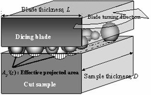
Figure 9. Vertical cross view of a dicing blade. Effective projection area, Ap’(z) is shown as total hatching area. 
Figure 10. Relationship between Ah(z) and Ap’(z) by considering the grain sizes, grain number and grain distribution. The theoretical feeding speed, S’, was estimated from the theoretical volume removal rate divided by the contacting area between the sample and the dicing blade. The theoretical volume removal rate is calculated from the effective projected area, Ap’(z), and the turning velocity of the dicing blade, V. The contacting area is equal to the dicing blade thickness, L, multiplied by the sample thickness, D.  (7) (7)
V is the turning velocity of the dicing blade, 60 m/s, L and D were 90 μm and 1.2 mm, respectively. By substituting the calculated Ap’(z) in equation (7), the theoretical feeding speeds, S’ were calculated. The calculated feeding speeds by equation (7), are 1.4, 4.1 and 6.5 mm/s for #1200, #800 and #500 dicing blades respectively as shown in Figure 11. The theoretical feeding speeds for various grain sizes were close enough to the empirical feeding speeds, which denote the calculation of feeding speeds by equation (7) is reasonable enough for a constant feeding-force system. The differences observed between empirical and theoretical feeding- speeds are considered to be due to the overlapping of matrix material in the effective projected area, Ap’(z) 
Figure 11. Calculated and empirical dicing-speeds for the first dicing line. Conclusions A theoretical calculation model for grindability was established by analyzing dicing speeds on a constant feeding-force dicing system. The theoretical dicing speed was calculated for different abrasive grain sizes using the turning speed of the dicing blade, together with the projection area, number and distributions of abrasive grains on the dicing blade surface considering spherical shape. The projection areas of diamond grains were calculated by using the Vickers Hardness of AlTiC, plowing load, number of abrasive grains and the distribution of grains on the dicing blade surfaces. The theoretical dicing speeds of different abrasive grain sizes, 5-12 μm (mesh number 1200, #1200), 10-20 μm (#800), and 30-40 μm (#500) for the first dicing line were 1.4, 4.1 and 6.5 mm/s, respectively. The empirical dicing speeds of dicing blades, #1200, #800 and #500 under 2.0 N constant feeding- force dicing system for the first dicing line were 0.95, 4.8 and 6.3 mm/s respectively, in fairly good agreement with the theoretical ones. It has been concluded that the grindability of dicing blades depends on the abrasive grains size, number and distribution on the surface of the dicing blade. Acknowledgements The authors wish to express their gratitude to the Japanese government for partially supporting this work through the 21st Century Center of Excellency (COE) Program of the Ministry of Education, Culture, Sports, Science and Technology. A part of this research was also supported by New Energy and Industrial Technology Development Department (NEDO), Japan. References 1. H. Gatzen, “Challenges in Machining Ultraprecision Pico Sliders”, Data Storage, 4 [8] (1997) 85-90. 2. H. Onishi, Y. Kondo, S. Yamamoto, A. Tsukuda, and K. Ishizaki, J. Ceram. Soc. Jpn, 104 [7] (1996) 610-613 (in Japanese). 3. Takata, “Kou Nouritsu Kou Kensakuhi Takousitsu Daiyamondo Toishi no Kaihatsu” Doctoral Dissertation of Nagaoka Univ. of Tech., (1998) 47-67 (in Japanese). 4. H. Kim, K. Matsumaru, A. Takata and K. Ishizaki, “Grinding Behavior of Silicon Wafer and Sintered Al2O3 by Constant Force Feeding Grinding System”, Adv. in Tech. of Mat. and Mat. Proc. J. (ATM), 5 [2] (2003) 50-53. 5. T. Adachi, K. Matsumaru and K. Ishizaki, “Fabrication of Highly Efficient Dicing Blade for Cutting Al2O3-TiC Composite”, J. Ceram. Soc. Japan, 114 [4] (2006). 6. K. Matsumaru, T. Adachi, H. Kim, A. Takata and K. Ishizaki, “Teiokuri Kensakuban ni yoru Seramikkusuno Cyou Heitan Usuita Kakou”, International Disk Drive Equipment Materials Association Japan News, [48] (2002) 8-11 (in Japanese). Contact Details | Kozo Ishizaki Department of Mechanical Engineering
Nagaoka University of Technology (Nagaoka Gijutsu-Kagaku Daigaku)
Nagaoka
Niigata 940-2188, Japan E-mail: [email protected] | Takuya Adachi Department of Mechanical Engineering
Nagaoka University of Technology (Nagaoka Gijutsu-Kagaku Daigaku)
Nagaoka
Niigata 940-2188, Japan | | Koji Matsumaru Department of Mechanical Engineering
Nagaoka University of Technology (Nagaoka Gijutsu-Kagaku Daigaku)
Nagaoka
Niigata 940-2188, Japan | |
|