The LaserNet Fines®-C (LNF-C), Figure 1, is a bench-top analytical tool that combines the oil analysis techniques of particle shape classification and particle counting in one instrument. The LNF-C analyzes hydraulic and lubricating oil samples from various types of equipment and machinery that are part of a machine condition-monitoring program. The monitoring is based primarily on the morphological analysis and the particle size distribution of the abnormal wear particles that are created from the internal components of the machine. The operator is presented with an assessment of particles found in the fluid sample and a history of previous results for the same equipment. LNF-C can be used as a stand-alone analytical instrument, or in conjunction with a full service oil analysis program.
Lockheed Martin Tactical Defense Systems developed the LaserNet Fines in cooperation with the Naval Research Laboratory for the Office of Naval Research as part of its Accelerated Capabilities Initiative for Condition-based Maintenance. The original LNF instrument was designed as a stand-alone instrument in a rugged, shock and vibration protected case meant for shipboard use. This version is known as the LaserNet Fines®-M (M for Military) and is no longer available. The LaserNet Fines®-C (C for Commercial) is a reconfigured and more affordable version that uses an external computer for control and data storage. Sample processing, software and results are the same for both the LNF-C and LNF-M. Therefore, in the following text we will refer to the instrument as the LNF, although it is the LNF-C model that is now commercially available.
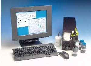
Figure 1. LaserNet Fines®-C Particle Shape Classifier and particle Counter
Shape Recognition Features of the LaserNet fines (LNF) Analyzer
As a particle shape classifier, the LNF provides the user with shape recognition of all particle greater than 20 µm by using a neural network. An algorithm sorts particles into the following categories: cutting, fatigue, severe sliding, nonmetallic and fibers. The shape recognition software also does a test for circularity so that bubbles and droplets greater than 20 µm are approximate results of free water based on this feature.
Particle Counting Capability of the LaserNet fines (LNF) Analyzer
As a particle counter, the LNF processes and stores thousands of images to obtain good counting statistics. Particles are sized directly and results can be displayed by ISO Code (>4 µm, >6 µm, and >14 µm), or other codes such as the NAS Code (5-15 µm, 15-25 µm, 25-50 µm, 50-100 µm and >100 µm). The direct imaging capability of this instrument eliminates the need for calibration with a test dust. Air bubbles greater than 20µm are ignored and the laser is powerful enough to process heavily sooted (black) oils.
The basic operating principle of the LNF is illustrated in Figure 2. A representative oil sample is taken from the lubricating system and brought to the instrument. The oil is drawn through a patented viewing cell that is back-illuminated with a pulsed laser diode to freeze the particle motion. The coherent light is transmitted through the fluid and imaged onto a digital CCD camera. Each resulting image is analyzed for particles, with several thousand images ultimately used to determine the characteristics of the suspended particles and to obtain good counting statistics. Concentrations are measured for particle sizes between 4 µm to over 100 µm.
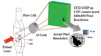
Figure 2. Basic Operation of LNF-C
Particle Size Dimensions and ISO Classification of Sample
LNF reports particle size in terms of maximum chord (maximum diameter) and also calculates equivalent circular diameter for compatibility with ISO cleanliness codes. Shape characteristics are calculated for particles greater than 20 µm, and the particles are classified into either a wear category or contaminant category. Classification is done with an artificial neural network that was developed specifically for the LNF system.
Shape Classification Capability of the LaserNet fines (LNF) Analyzer
Shape features were chosen to give optimal distinction between the assigned classes of fatigue, cutting, severe sliding, nonmetallic, fibers, water bubbles, and air bubbles. An extensive library of particles, which were identified by human experts, was used to train the artificial neural network. An example of the shape classification capability of LNF is shown in Figure 3.
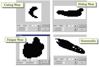
Figure 3. Shape Classification of LNF
Calibrating the LaserNet Fines (LNF) Analyzer to ISO 4406:1999 Compliance
The LNF was designed primarily as an automatic wear particle shape classifier and trending tool to assist in condition monitoring programs. However, because of its direct imaging capability it is also an accurate particle counter. It is ISO 4406:1999 compliant. The LNF does not require calibration using NIST Standard Reference Material (SRM) 28062 because it directly images the particles. During manufacture, magnification is calibrated to objects of known linear dimensions. This is unlike conventional particle counters and eliminates the costly requirement to be sent back to the factory for an annual calibration.
Particle Counting According to NIST SRM 2806 Standard
It is noteworthy that the LNF correctly counts the NIST SRM 2806 (or its derivative, the commercially available PartiStan). The NIST determined counts for SRM 2806 by capturing the particles from SRM 2806 hydraulic fluid on a membrane filter and counting the particles by using a scanning electron microscope (SEM). Particles appear solid when viewed by an SEM, even though the particles might be transparent to visible and near visible light. Therefore, a SEM fills in the area of particles that might otherwise be partially transparent when passing by the sensor of a conventional automated laser light blockage particle counter. Automated light blockage particle counters correctly measure SRM 2806 because this is the very fluid they are calibrated with. On the other hand, the LNF correctly measures the SRM 2806 because it is an automated microscope calibrated to a known linear dimension, a much more fundamental calibration than using an arbitrary calibration fluid. The LNF directly images each particle whereas an automated light blockage particle counter measures only how much light is blocked. In essence, the LNF achieves the same counts that the NIST did for the SRM 2806 from first principles. An automated light blockage particle counter gives no information about particle shape.
A discrepancy may occur when comparing wear particle counts measured by an LNF with the counts from a conventional automated light blockage particle counter. The metal particles, being solid, will block more light proportional to their size than will transparent particles. Therefore, the light blockage particle counter will overestimate the size of metallic particles. The LNF imaging may be thought of as an automated microscope system that captures digital images of the particles as they flow through the cell. The LNF fills in any translucent areas of fibers or nonmetallic particles that it may encounter in a sample, and calculates both the equivalent circular diameter and maximum diameter values for hydraulic cleanliness (ISO CODES) and wear particle trending, respectively.
NAS 1638 Classification of the LaserNet Fines (LNF) Analyzer
Because the LNF instrument records the total size resolution of all the particles that it records, it is able to report NAS and NAVAIR cleanliness codes. NAS 1638 was developed by the Aerospace Industries Association of America, and is similar to ISO 4406 in that it classifies cleanliness according to pre-defined particle counts of certain particle sizes. NAVAIR 01-1A-17 is the U.S. Navy standard for particulate cleanliness. A suspension of test dust in oil such as NIST SRM 2806 may be measured by the LNF periodically to verify proper operation of the instrument, but the Standard Reference Material is never used to calibrate the LNF. A fluid check dialog is available, Figure 4, to show performance comparisons to certified NIST standards with cumulative graphical results.
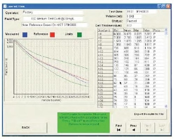
Figure 4. Calibration Verification Software Dialog
The LaserNet Fines became commercially available in 2000 and since then more than 200 instruments have been commissioned for various military and industrial applications in 38 countries around the world. Every LNF must successfully measure check fluid as described above, but a systematic test of LNF reproducibility has never been performed. This paper describes such a test.
Case Study - LaserNet Fines Reproducibility Test for Particle Counting & Shape Classification
This application note presents data recently generated in reproducibility and repeatability tests performed on five LaserNet Fines (LNF) Wear Particle Classifier and Particle Counter instruments. The test was conducted with Medium Test Dust dispersed in mineral oil.
A master oil sample was prepared by mixing Medium Test Dust with approximately 700 ml of purified mineral oil with a viscosity of 63 cSt at 40°C. The mineral oil was initially analyzed on the LaserNet Fines to check for particulate contamination and it was found to be very clean with a 13/11/6 ISO code. It contained only 48 particles per ml greater than 4 µm. A one U.S. quart (950 ml) container was used to prepare the master sample. Approximately ¼ of the mineral oil was poured out of the container before the Medium Test Dust was added. The oil was removed to allow the contents to be easily shaken so that the dust would be well dispersed throughout the approximately 700 ml of mineral oil remaining in the container. The master sample with the Medium Test Dust was then used to prepare five identical samples.
Five 125 ml plastic wide mouth sample bottles were opened and lined up on a lab bench. Immediately after vigorously shaking the master sample, about 10 to 12 ml of master sample was poured into the first plastic sample bottle, then the second, then the third, etc. As soon as the first 10 or 12 ml was poured into each of the 5 sample bottles, the process was repeated 7 or 8 times until each bottle was approximately ¾ full. The purpose of this procedure was to make the particle population in each of the 5 bottles as similar as possible.
Analysis of Samples with the LaserNet Fines (LNF) Analyzer
The five LNF’s chosen for this test were a combination of old and new instruments. The oldest unit, S/N 0021, was manufactured approximately 6 years ago and S/N 0226 and S/N 0239 were brand new instruments removed from stock for the purpose of the test. The other two instruments, S/N 0079 and S/N 0186 have been in use for multiple years. To verify proper operation, a check fluid was run through each of the five LNF’s. The LNF check fluid used is a PartiStan, Medium Test Dust in Hydraulic Fluid; the commercial version of NIST Standard Reference Material 28062.
Reproducibility Testing of the LaserNet Fines (LNF) Analyzer
The reproducibility testing was conducted in such a way as to randomize the effects of the sample bottles as well as the order from which the samples were withdrawn from each bottle. Each of the 5 sample bottles was run once on each instrument. Each instrument sampled one of the bottles first from one of the five bottles, each instrument sampled one of the bottles second from one of the five bottles, each instrument sampled one of the bottles third from one of the five bottles, etc., until five samples were run from each of the five bottles. Each time, before inserting the LNF sipper tube into the sample bottle to pull sample into the LNF for measurement, the sample bottle was vigorously hand-shaken to thoroughly disperse the particles it contained. Then air bubbles were removed by placing the bottle in an ultra-sonic bath with a power density > 4000 W/m2 for two minutes. The sample bottle was then brought
promptly to one of the five LNF’s to begin the measurement procedure.
Analytical Results from the LaserNet Fines (LNF) Analyzer
The analytical results from the five samples as analyzed on the five LNF’s are shown in Tables 1 through 7.
- Table 1 – Reproducibility for this test is defined as test results obtained with the same test method on identical samples and on different instruments. Table 1 shows the order in which the samples were run, from which bottle each sample was withdrawn, on which instrument the sample was run and the corresponding analytical result. The reproducibility for the 25 runs is summarized as an average, standard deviation and relative standard deviation for each particle size range. The percent RSD (Relative Standard Deviation) is 3.2% for particles greater than 4 µm. The counts are for particles with an equivalent circular diameter greater than the stated size. The LNFsoftware converts the pixel image of each particle into an area by filling in any transparent interior pixels. An equivalent circular diameter is then calculated from the resulting area.
- Table 2 - Repeatability is defined as test results obtained with the same test method on identical samples and the same instrument. Table 2 shows the repeatability for individual LNF instruments. As one would expect, repeatability on the same instrument is better than reproducibility on multiple instruments, and under these conditions, the percent RSD (Relative Standard Deviation) is an average of 2.7 % for particles greater than 4 µm.
- Table 3a – This table compares averages of the 5 runs made on each instrument. It compares performance among the 5 instruments for particle counting.
- Table 3b – This table compares the averages of the particle counts of the five samples taken from each bottle.
- Table 3c - This table compares the average of the different “layers” taken from each sample bottle. Layer 1 being the first sample taken from the bottle, Layer 2 the second sample, etc. This attempts to determine if there are any differences among the sequence of when the samples were taken from each bottle.
- Table 4 - This table presents data for the particle shape classifications made during the 25 runs.
- Table 5 - This table presents data for particle shape classification for individual instruments.
- Table 6a - This table compares averages for all five runs made on each instrument for shape classification categories. This table gives an indication of how closely shape classification agrees among different instruments.
- Table 6b - This table compares the averages of the shape classification categories of the five samples taken from each bottle.
- Table 6c - This table compares the averages of the shape classification categories for the different “layers” taken from each sample bottle. Layer 1 being the first sample taken from the bottle, Layer 2 the second sample, etc. This attempts to determine if there are any differences among the sequence of when the samples were taken from each bottle.
- Table 7 - This table compares the NIST SRM 2806 particle distribution with the LNF results.
Analysis of Results from the LaserNet Fines (LNF) Analyzer
The analysis of the results obtained from the LaserNet Fines (LNF) Analyzer
- Table 1 shows, as expected, that, in general, as the particles become larger, the RSD increases. The RSD becomes rather meaningless for the largest particles since there are so few present.
- Table 2 data show that repeatability for individual instruments is better than reproducibility among several instruments, as would be expected.
- Table 3a data show that the instruments are fairly consistent when sizing particles.
- Table 3b data indicate that there appear to be little difference in particle size and concentration among the five bottles of test oil used in this study.
- Table 3c indicates there is little difference whether the sample was taken first or last from each of the bottles.
- Table 4 data show that RSD’s are not nearly as low for shape classification as for particle counting for the smallest particles, but the LNF software does not attempt particle recognition until the particles are at least 20 µm in chord length (maximum diameter). The RSD for simply counting particles >20 µm is not so low either, at 11.0 %. Of note is that the combined total of particles in the cutting, sliding, fatigue and nonmetallic categories (C+S+F+N) shows reasonable reproducibility at 8.5 %. The RSD for nonmetallic particles is 13.0 %, only slightly higher than the RSD for all particles >20 µm at 11.0 %. Please note that the number count for all particles >20 µm is about one-third the count for the sum of cutting, sliding, fatigue, and nonmetallic particles. The main reason for this is that the particle count of particles >20 µm is determined by equivalent circular diameter. The sizes of cutting, sliding, fatigue, and nonmetallic particles are determined by maximum diameter (maximum chord length). Therefore, any particle not exactly spherical will have an equivalent circular diameter less than its maximum chord length. For example, the area of a sliver 30 µm long may have enough area to only give an equivalent circular diameter of 10 µm.
- Table 5 data indicate individual instrument repeatability for particle categorization is superior to the overall reproducibility for the 5 instruments.
- Table 6 data indicate that differences in particle shape classification appear to be due to differences between instruments rather than differences between the particle population in each bottle or when the sample was withdrawn from each bottle.
- Table 7 data indicate that the particle distribution measured by the LNF is consistent with the particle distribution of NIST SRM 2806. The median counts for SRM 2806 are 6095 particles per ml > 4 µm. The concentration of MTD in the fluid used in this test was approximately 12.3 times higher at 74,986 particles per ml > 4 µm. If a factor of 12.3 is applied to the median counts for the other size categories reported for SRM 2806, the resulting concentrations compare favorably with the data produced by the LNF's. Another way to compare this data is to divide the LNF result by the NIST median count number for each size category. Again, the resulting ratios indicate that the LNF reports substantially the same distribution as stated for SRM 2806.
Summary
Testing of 5 LNF instruments indicate excellent particle counting reproducibility and adequate particle shape classification reproducibility so that data from one LNF may be reasonably compared to data from any other LNF.

This information has been sourced, reviewed and adapted from materials provided by AMETEK Spectro Scientific.
For more information on this source, please visit AMETEK Spectro Scientific.