| When you are sailing at the elite level in a one-design class of boat such as Laser dinghies, finding that extra edge over the competition is hard. Not only do you need to be supremely fit and agile, you are looking to have equipment that will meet the demands of high performance sailing. Design Aspects Sailing a Laser dinghy is probably the most competitive form of one-on-one sailing that any dinghy sailor can aspire to. Today there are more than 170,000 of these dinghies sailed world-wide. The class rules of this one-design dinghy have been designed to ensure that all competitors are matched evenly against one another with the same equipment, and that it is the skill of the sailor that wins through. Even so there are one or two areas where an individual sailor can bring technology to bear to his or her advantage. To get the best from your boat you need to concentrate your mass near the centre of gravity of the whole structure and minimise the pitching effects. Removing weight from the ends of a boat or the top section of the mast will naturally help. And in the Laser dinghy - which is of glass fibre construction - about the only scope you have for this is with the tiller and tiller extension. It is now becoming increasingly common for both these items to be made in carbon fibre reinforced plastic (CFRP) rather than the traditional aluminium that is sold with every new boat. Composites in Small Boats So what does a Laser sailor look for in these parts that will give him the edge? To answer this you must first understand the idiosyncrasies of the design of the boat. While beating to windward in anything of a breeze, you are looking to extract as much power from the sail as possible. Keeping the leach (or back edge) of the sail tight is essential to stop spilling wind. The novel design of the aft traveller, which controls the mainsheet (rope), directly governs the power you can get from the sail. Because the rudder tiller passes directly beneath this traveller, figure 1, it is preferable to have the tiller as low to the deck as possible. In this way you can in turn keep the boom low and the leach tight. Any tiller must therefore be very slim in profile, low to the deck and as stiff as possible so that it will not deflect. The high strength, high stiffness (Young’s modulus) and low weight of (CFRP) makes it the natural material of choice for this application. | 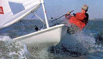
| | Figure 1. A competition laser dinghy. | Similarly, in the Finn single-handed dinghy, one of the oldest racing dinghies, there have been moves made to bring this dinghy up to date with more modern materials. Consequently it is no surprise to see the mast made of (CFRP) and, even the headboard on the sail is now (CFRP) This is all in the interest of reducing the pitching moment of the boat so that, should the helmsman run into the back of a wave on a downwind leg, the mast will not fly forward or pitch pole the whole boat Composites in Large Boats In big boats, the benefit of composites has long been recognised in the construction of hulls. Classic examples of such boats that have made extensive use of carbon fibre include Mari Cha III, which broke the transatlantic speed record at the end of 1998. This boat made extensive use of structural carbon and aramid epoxy materials in the hull which had an overall thickness of about 200 mm. Pete Goss was also planning to make a record breaking attempt with a catamaran made from (CFRP) the Goss Challenger. His aim was to be the person to bring home the cup from the ultimate Millennium Race, that started on December 31st in the year 2000. Prior to that he hoped to break the Jules Verne record in the winter of 1999/2000. Carbon Fibre Boat Components As (CFRP) has come of age, so more and more applications have been found that take advantage of its exceptional properties. Key fixtures and fittings of the boat are now being made from these materials. Steering wheels and wind transducers are some of the most recent advances. Manufacturing Aspects Since many offshore yachts are individual designs, or at least made in only small production runs, the cost of tooling has always been a major part of the total cost. Similarly with items like steering wheels. These are often custom made to fit a particular space envelope in the cockpit of the hull. Making individual moulds for each and every different-sized steering wheel would be prohibitively expensive. By adopting a modular approach it has been possible to make steering wheels of different sizes from just a few key components. Standard components comprise the inner and outer hub, spokes (made to one length but cut to the required size) and spats (to join the spoke and wheel rim). The only item that has to be custom made is the wheel rim. These wheels, developed in just 15 days, were first shown at the Amsterdam Boat Show in November 1998 by Whitlock Marine, figure 2, and are now in full production. | 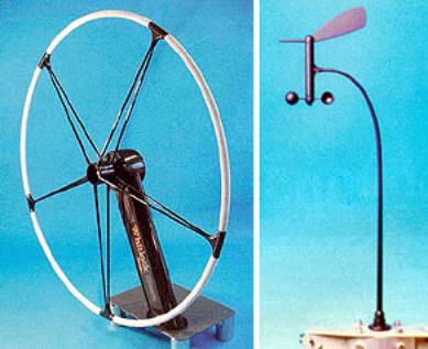
| | Figure 2. Carbon fibre reinforced steering wheel and wind transducer. | Instrumentation is becomingly increasingly sophisticated on offshore racers and cruisers. However, there is still a need to know the fundamentals, like direction and speed of the wind. To get an accurate reading of both speed and direction, any transducer should ideally be placed well out of any interference from either the mast or sail, as updraught from either of these sources can affect the true readings. In an effort to overcome this a forward-looking wind transducer is mounted at the head of the mast, figure 2. Such a transducer is largely out of sight and mind of the helmsman until something goes wrong. It sits some 15 m in the air and can be subject to 50 g loadings when pitching and rolling in a violent storm. Weighing just 60 g these (CFRP) arms carry the direction vane an anemometer and must be capable of taking these high ‘g’ loadings. Origins of Carbon Fibre Composites Carbon fibre composites came of age in the aerospace industry. Their true worth was recognise many years ago when aerospace engineers saw the weight savings that could be made compared with traditional materials like metals. Table 1 illustrate this quite clearly by showing the structural efficiency of a variety of materials that might be used in bending and compression (as in a strut). Table 1. The efficiency of various materials in different roles. | | | Steel | 210 | 7.8 | 26.9 | 5.2 | | Titanium | 120 | 4.5 | 26.7 | 5.2 | | Aluminium | 73 | 2.8 | 26.0 | 5.1 | | High Strength CFRP | 138 | 1.6 | 86 | 9.3 | Why use CFRPs? It will be noted that for the majority of traditional structural materials - steel, titanium, aluminium the specific stiffness (E/ρ) is constant, whereas CFRPs offer far higher efficiencies for stiffness or deflection critical structures. When carrying a compression load, as in a column, the efficiency of the structure is governed by √E/ρ and here again the benefit of using carbon fibre composite materials is demonstrated. While the basic stiffness of steel is far greater than (CFRP) the massive weight saving that can be made by using the material provides a tremendous driving force to choose (CFRP). No matter which metal is chosen for use, the specific stiffness (Young’s modulus divided by specific gravity) of all metals remains stubbornly fixed at 25-26 GN.m-2. It is not until we look at ceramics and high performance fibres that this barrier can be broken. And with a specific stiffness of at least 86 GN.m-2 it is easy to see why aerospace engineers wanted to take full advantage of this so-called wonder material. Price has for a long time been the Achilles heel associated with (CFRP). Fortunately, with the increasing demand for (CFRP) the price has steadily declined over the years with increasing applications in the sporting goods area and more general engineering industries. Other Benefits of using CFRPs Of course the other great benefit of using (CFRP) is the fact that the structural properties can be tailored to the application. Because the basic building block material is a unidirectional tape or fibre, or a woven fabric, individual plys can be laid down and oriented in the direction of the principle stresses. Further, these plys can be dropped off, or staggered, along the length of a structure such that the fibres really are where they are wanted - in much the same way as the branch of a tree has more material at the base than it does at the tip. Manufacturing of CFRPs And when it comes to manufacture, there are techniques suited to one-off and medium or high volume applications. Parts such as tillers, steering wheels and wind transducers for small and large boats alike are all readily made using low-cost metal moulds and internal pressure bags. At the other extreme, high volume parts can be stamped using thermoplastic composite materials. By coupling this with injection moulding, hundreds of parts per hour can be readily achieved. Summary The combination of stringent performance demands, materials with high specific properties and competitive manufacturing techniques suited to both low and high volumes will ensure the growth of advanced composite materials. |