Using thin films of dielectric materials in optical coatings have long been common practice in the glass and optics industries. For example, Bragg mirrors in laser cavities are formed using alternating low and high refractive-index layers. They are also used in display screens where layers of magnesium fluoride are used as antireflection coatings.
However, in the last 20 years, more and more materials have emerged, significantly widening the range of optical coatings available in the market. Such coatings do not necessarily planar or fully dense—leading to light scattering—and they may be intended to function at nonnormal angles of incidence, for which s- and p-polarized light behave differently.
In the case of optical coatings, especially those that receive direct light into or light from non-normal angles, it is important to define the polarization-, angle-, and wavelength-resolved transmittance and reflectance. The automated reflectance/transmittance analyzer (ARTA) from PerkinElmer serves as a drop-in accessory for the LAMBDA™ 950 and LAMBDA 1050 UV/VIS/ NIR spectrophotometers, which are dual-beam, dual-monochromator instruments (Figure 1).
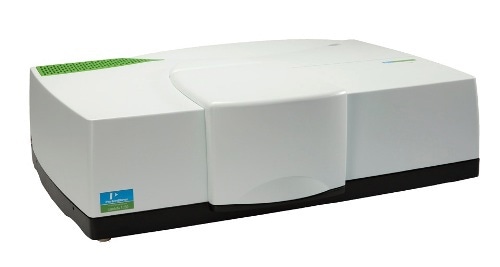
Figure 1. LAMBDA high performance UV/Vis/NIR spectrophotometer.
The ARTA utilizes a goniometer to independently rotate an integrating-sphere detector with respect to the sample and to rotate a sample with respect to the beam. Spectra can be acquired for p- and s-polarized light in the 250– 2500nm wavelength range for detection angle and incidence angle pairing. A user-specified table of these measurements is automatically run by the ARTA accessory.
This article explores the performance of the 3M® long-pass optical film. 3M® uses an extensive range of plastic films, which includes many transparent polymer layers of different refractive indices and thickness that collectively reflect and transmit selected parts of the solar spectrum for applications such as low-emissivity windows glass.
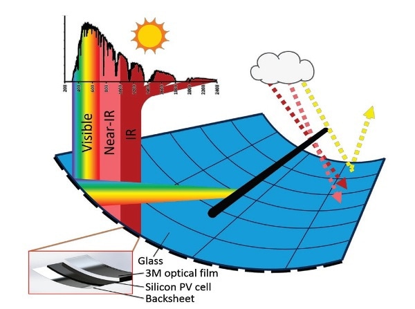
Figure 2. Rendering and schematic of the proposed curved photovoltaic module. The 3M® visible mirror film would make the module appear mirrored at visible wavelengths but black at near-infrared wavelengths.
In this analysis, the selected visible mirror film absorbs UV light of 750nm wavelength. Specific attention was given to incorporate this film within a curved silicon PV module (Figure 2) as the silicon solar cells convert radiation, of energy close to their bandgap, into electricity with more than 40% efficiency. However shorter wavelengths are also converted, with relatively lower efficiency with the excess energy lost as heat.
In the solar energy sector a chemical vapor deposition process is used for growing the zinc oxide coatings, which tend to develop a pyramid-like texture. The surface is used to disperse light in thin-film solar cells. Holographic filters divide the solar spectrum into clear, discrete bandwidths, and a novel type of multi-junction solar cell can be formed by placing wavelength-tuned photovoltaic (PV) cells at these foci.
The front portion of a silicon solar cell is covered with silicon nanocylinder coating, which serves as a Mie scatterer. The Mie scatterer reduces reflection and therefore increases the absorption in solar cells for different polarization and angles of incidence.
When the 3M® optical film was placed in front of the solar cells, the shorter wavelengths that are poorly used are reflected to a focus point where another radiation-adjusted solar collector was placed, whilst the infrared (IR) wavelengths are transmitted to the cells. The curved PV module is positioned on a one-axis tracker and follows the sun from East to West. In contrast, the 3M® optical film receives sunlight at 0° to 60° angles of incidence over the course of the year. In order to establish the yearly power output of the whole solar collector it is critical to define the polarization, angle- and wavelength-resolved performance of the 3M® optical film.
Experimental Procedure
An optional 150mm integrating sphere accessory is also fitted into the LAMBDA 950 and LAMBDA 1050 UV/VIS/NIR spectrophotometers. Both InGaAs and silicon detectors are included in the Spectralon-coated integrating sphere so that precise spectra can be acquired from 200 to 2500nm. One way to determine the total transmittance, total reflectance, diffuse transmittance and diffuse reflectance of a substrate, film or liquid is to place the sample at the integrating sphere’s exit or entrance port and remove the specular port in the case of diffuse measurements.
The integrating sphere accessory can be rapidly exchanged with the ARTA accessory (Figure 3) to achieve a more complete analysis of the angular dependence of transmission and reflection for random angle of incidence.
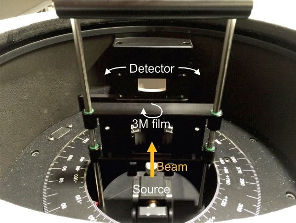
Figure 3. Photograph of the ARTA with the 3M® film (which looks like a mirror since it reflects visible wavelengths) mounted in the sample holder. The detector is shown without a slit aperture, which corresponds to an acceptance angle of 20°.
Also the ARTA accessory uses an integrating sphere with InGaAs and PMT detectors and the same is placed on a goniometer so that it can rotate 340° around the sample in the horizontal plane and collect the light falling within its width entrance aperture. This can be adjusted accordingly.
Independent of the detector, the sample placed on the goniometer is allowed to rotate so that users can select random angles of incidence and detection. ARTA control is incorporated within the UV Winlab software to allow user-specified table to run automatically.
In this study, the LAMBDA 950 spectrophotometer was used to collect angular and total- resolved transmittance and reflectance spectra of the 3M® visible mirror film. In the case of total transmittance and reflectance spectra the 3M® visible mirror film was positioned at the exit or entrance of the 150mm integrating sphere accessory, and with the aid of unpolarized light, spectra were obtained over 250 to 500nm.
In order to perform angular-resolved measurements, the film was placed in the ARTA’s goniometer holder and spectra were individually collected from 250 to 2500nm for p- and s-polarized light, as shown in Figure 3.
The angle of incidence was changed from 5° to 85° in increments of 5° and the movement of the detector was coordinated in such a way that the position of the detector always matches with the specular beam. In other measurements the angle of incidence was fixed and the detector rotated around the sample in 1° increments.
In the latter experiments, slits of differing thickness were positioned in front of the detector to vary the measurements’ angular resolution.
Results and Discussion
The integrating sphere accessory of the LAMBDA 950 instrument was used to calculate the specular and diffuse (total) transmittance and reflectance of the film at normal incidence. This was done before the ARTA accessory could be used for detailed analysis of the 3M® optical film. In Figure 4, the results show that the film displays the required reflecting-to- transmitting transition at 750nm wavelength, with an IR transmittance of 90% and a visible reflectance of almost 100%.
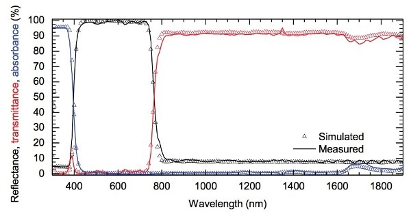
Figure 4. Total reflectance and transmittance spectra of a 3M® visible mirror film measured with the 150 mm integrating sphere accessory. Also shown are the simulated spectra calculated by 3M®. The absorbance of the film was calculated as 1-R-T.
3M® modeled the same film by utilizing the known refractive indices and widths of the polymer layers, and the replicated spectra corresponds with the quantified spectra to within 2% at most wavelengths.
Given that the film is naturally planar with a low surface roughness the total reflectance must be similar to the specular reflectance, which was determined with the ARTA accessory at the same 8° angle of incidence.
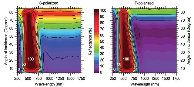
Figure 5. Angle-resolved reflectance spectra of a 3M® visible mirror film for s-polarized (left) and p-polarized (right) Picture. The reflectance color scale is common to both plots. Spectra were measured with the ARTA accessory using 5° steps in the angle of incidence. The detector was rotated at each angle of incidence so as to always receive the specularly reflected beam.
Figure 5 shows the specular reflectance resolved using the polarization and the angle of incidence as a contour plot, a horizontal slice collected above the x-axis appeared to be the reflectance in Figure 4. It should be noted that the angle of detection was always double the angle of incidence for these kinds of measurements.
The transition from reflecting to transmitting continues to remain sharp up to angles of incidence of 50° in the case of both polarizations, but nevertheless has a subtle blue shift. In applications such as solar energy conversion, this will have the effect of moving a small amount of light combined to the solar collector at its focus and to the curved PV module.
Whilst this is not convenient, proper engineering would make this acceptable. For angles of incidence of over 50° the transition disappears in the case of s-polarized light and the film loses its function as a spectrum splitter. The outcome of this effect is that the curved PV mirror will not operate adequately during summer or winter season for latitudes more than 30°.
After the optical performance of the free-standing film was characterized, film samples were laminated between silicon wafers and glass substrates using various encapsulants to approximate the final, curved, spectrum-splitting photovoltaic module. Three such laminates are shown in Figure 6a suggesting that the film can continue to remain planar or become wrinkled to differing degrees during the lamination process based on the encapsulant used and the process details.
The variable acceptance angle of the detector aperture combined with the goniometric nature of the ARTA accessory makes it possible to rapidly measure the angular distribution function of scattered light in reflection or transmission.
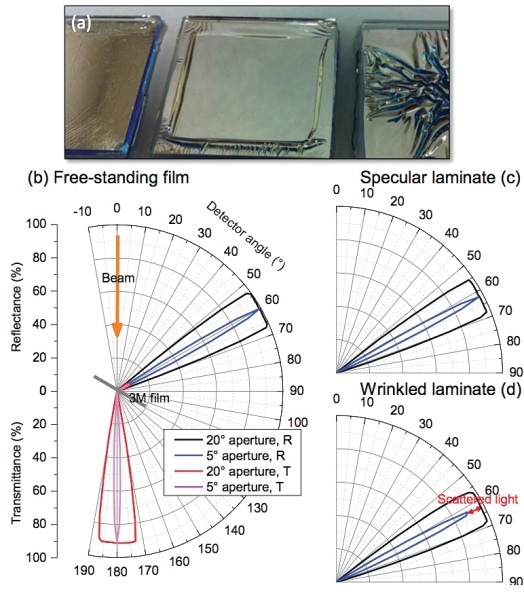
Figure 6. (a) Photograph of three glass/3M® film/silicon wafer laminates with different encapsulants. (b) Reflectance and transmittance of the free-standing 3M® film as a function of the detector angle. In these polar plots, the radial length of the signal corresponds to the intensity; the outermost circle is 100% reflectance or transmittance. In addition, the beam appears to have a wider spread as the detector aperture is increased because for an, e.g., 20° acceptance angle, all of the light is still detected when the detector is <10° from the specular angle. Reflectance of the (c) visibly specular laminate in the middle of the photograph in (a) and the (d) visibly wrinkled laminated in the left of the photograph in (a).
Figure 6b-d which appear on the next page, displays such data for two laminates—one visibly planar and the other visibly lightly wrinkled—as well as a free-standing film. 600 nm light, which is in the middle of the reflected band, was used for all samples; the free-standing film was also measured at 1100 nm, where the film transmits, for reference (this was not possible with the laminates because the silicon wafer absorbs this light). To perform these measurements, the angle of incidence was held constant at 30° while the detector automatically circled around the sample. The freestanding film and planar laminate show near-unity reflectance
at the at the specular angle. The wrinkled sample also reflects all light within a 10°-half-angle cone, but only 89% within a 2.5°-halfangle cone; the wrinkles clearly reduce specularity. The scattered light would miss the focus of the curved photovoltaic module, essentially reducing the concentration of light that arrives at the solar collector placed there.specular angle, consistent with Figure 5, even when the detector aperture is closed down to a 5° acceptance angle. That is, all light is reflected within a 2.5°-half-angle cone centered
Conclusion
With the help of the LAMBDA 950 spectrophotometer equipped with the ARTA accessory, the 3M® visible mirror film was assessed for possible applications in a new curved PV module. Using the ARTA accessory for angle-resolved transmittance and reflectance measurements suggested that the free-standing 3M® optical film serves as a suitable optical filter for angles of incidence of up to 50° as well as for p- and s-polarization.
At present the ARTA-generated spectra is being used to approximate the yearly energy output of a power plant using the curved PV modules with thermal receivers at their foci. Both yearly and daily movements of the sun and the corresponding difference in angle of incidence on the curved PV module were taken into account.

This information has been sourced, reviewed and adapted from materials provided by PerkinElmer.
For more information on this source, please visit PerkinElmer.