An unsatisfying compromise has to be made between acceptable throughput and sufficient data coverage when measuring high-slope machined parts, since metrology tools usually involve some sort of tradeoff between measurement speed and slope acceptance. For instance, for optical systems, while higher-NA objectives have higher slope acceptance, they usually have smaller fields of view (FOV). This results in more individual measurements if the region of interest exceeds a single FOV.
Large-departure and recessed features bring in an extra challenge of imposing a minimum working distance. This also generally involves a tradeoff with slope acceptance.
Machined parts are generally measured by coherence scanning interferometry (CSI). CSI provides non-contact areal topography maps with typical single-measurement topography repeatability of less than one nm on smooth, high-reflectivity surfaces [1]-[2]. A usual selection of objective magnification varies from about 1X to about 100X. Ideally, the highest local slope θmax falls within the specular limit of the objective NA so as to satisfy the condition, NA > sin (θmax). However, in actual practice, a lower-NA objective may be required due to the limitations of minimum working distance or field-size/throughput, or due to cost and availability considerations. Fortunately, quantifying slopes beyond the specular limit can be enabled if some light is scattered (usually by surface roughness) and the measurement is adequately sensitive. However, in the past, it has often been found difficult to measure high-slope parts by CSI, even in such conditions.
Recent technological developments substantially improve the baseline sensitivity of CSI and enable high-dynamic-range operation. This enables measuring recessed or high-slope features that were earlier inaccessible, or over larger FOVs for enhanced throughput.
Measurement and Analysis
A modern commercial CSI microscope was used to measure various machined parts [3]. Figure 1 schematically shows the operation of CSI, which works by scanning an interferometric objective relative to the sample being measured, generating localized interference patterns defining sample heights at all pixels of the camera. Thus, areal topography data is generated by a single scan at corresponding positions of best focus over the full field of the camera. Any type of interferometric objective can be used, including Michelson, Mirau, Linnik, or wide- field [4]-[5] objectives.
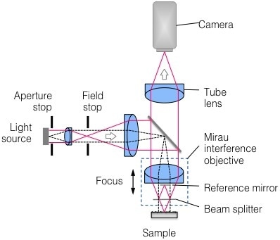
Figure 1. Schematic representation of Coherence Scanning Interferometry
The baseline data acquisition time, for the results presented in the article, is about 0.14 seconds per micron scanned. Raw height data are represented in all surface plots, with no masking, smoothing, or interpolation of missing data points. Dynamic noise reduction (DNR) was used to detect particularly weak signals, allowing a user-specified trade-off between sensitivity and throughput while preserving full lateral and vertical resolution [6].
Slopes Beyond the Specular Limit
A diamond-turned cone with an included angle of 90° is shown in Figure 2, where the cone has an outermost diameter of 4 mm, and relatively low surface roughness (Sa ~ 1.1 nm, as measured at normal incidence with a 10X Michelson objective). An objective with NA > 0.7 would be needed to accommodate the 45° slopes within the specular limit. However, in practice, this would involve stitching more than hundreds of FOV, may be with unacceptable throughput.
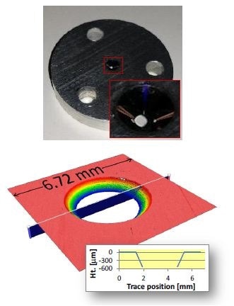
Figure 2. Measurement of 5-mm-diameter diamond-turned 90° cone in a single FOV. Top: photograph of part; bottom: measured height map.
A low-mag objective with NA well below 0.7 is needed to measure the cone within a single FOV. Using the traditional CSI for such a measurement might yield only a small amount of data. However, a valuable hint may also be provided: data at slopes above the specular limit means scattered light can be detected.
An almost-full data coverage is achieved by employing a 2.5X Michelson objective (NA = 0.075) together with 4X DNR (16X increase in baseline measurement time). These data are perfect to measure roundness and cone angle.
Spherical features have slopes of almost 90°, and are found in various applications, such as sealing surfaces and ball bearings. Measurement of spherical features becomes more difficult with increasing diameter: high slopes are needed for increasing FOV and working distance.
A 3-mm-diameter fuel-injector sealing ball, as measured in a single FOV with a 5.5X Michelson (NA = 0.15), is shown in Figure 3. An almost-full data coverage is achieved for local slopes more than 60°. The same objective is used to measure surface roughness (Sa), which is about 0.1 µm.
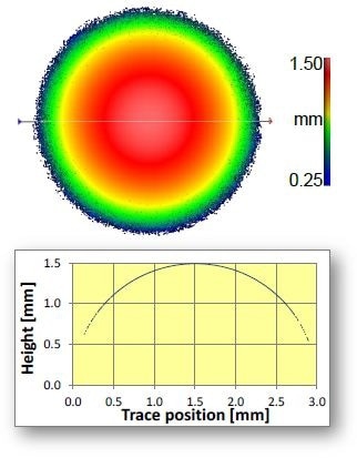
Figure 3. 3-mm-diameter sealing ball measured in a single FOV for local slopes up to 60°
Even when stitching is required, access to larger FOVs is advantageous. These include improved throughput, and faster targeting of functional surfaces and registration to datum surfaces. Using less number of FOVs also decreases the form error, which are caused due to stitching multiple slivers of data from smaller-aperture height maps.
A diamond end-mill [7] exposed to wear experiments in three locations and generating local slopes exceeding 70° is shown in Figure 4. It may appear that this may require stitching hundreds of high-NA measurements. However, complete data coverage was achieved by stitching only ~20 FOVs employing a 20X Mirau objective (NA = 0.4, specular limit ~23°), resulting in 0.4-µm lateral sampling (0.9-µm optical resolution) and nm-scale vertical resolution over the entire tool length with a total measurement time of a mere 9 minutes.
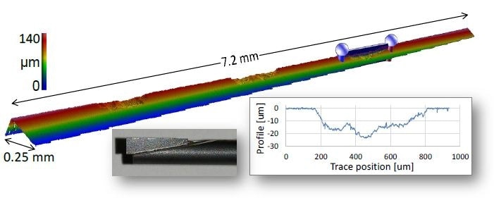
Figure 4. End-mill measured with 0.4 µm lateral sampling over 7.2-mm length and 145-µm scan range in about 9 minutes. Photograph of part is shown in lower left inset.
Success in measuring slopes more than the specular limit relies on several contributions, including spatial-frequency-dependent variations of the surface roughness and the Sa of the sample.
Recessed High Slopes
Sometimes high-slope features are recessed, residing some distance below a neighboring feature. Common instances include cones inside bores and shoulders along the exterior of a shaft. Recessed features act as sealing or mounting surfaces, with corresponding critical parameters such roundness, radius, and angle.
An objective with adequate working distance for accommodating the recess depth is needed to optically measure these critical parameters. This reduces the options to lower-NA objectives, which forces measurements to be taken by using whatever scattered light available. It would have been impractical to use traditional CSI to measure some extreme cases of recessed high slopes.
A photograph of an unfinished fuel injector with surface roughness Sa ~ 1 µm is shown in Figure 5. A shoulder in which the fuel injector mounts against an engine block is indicated by the highlighted region. The geometry of this shoulder is a crucial factor to ensure proper sealing, and can be characterized by the circumferential radius that is formed at the intersection of two steep-slope regions.
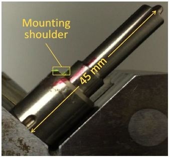
Figure 5. Photograph of fuel injector, with mounting shoulder region outlined in yellow
Earlier, the measurement of the shoulder region would have required stitching several higher-magnification measurements as well as avoiding mechanical interference with the rest of the part. A measurement captured in a single FOV of a specialized 5X Michelson (NA = 0.12) with a working distance of 40 mm is shown in Figure 6. An almost-full data coverage is achieved despite local slopes up to 45°.
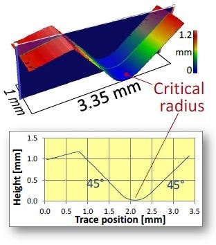
Figure 6. Measurement of shoulder region of fuel injector, highlighting radius critical for proper sealing with engine block
Figure 7 depicts an electrical feed-through assembly consisting of a number of ~ 1-cm pins secured by glass cladding that is recessed by ~ 1 mm within a metal housing. Other than the obstructing pins, the difficulties in the measurement of the glass profile include comparatively weak scattering due to low roughness and refractive index, and moderate local slope up to ~ 15°.
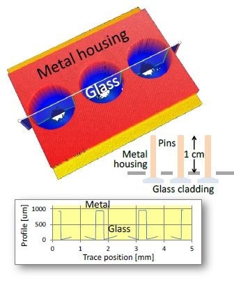
Figure 7. Electrical feed-through assembly. Of primary interest is the glass cladding, recessed below the metal housing along with pins extending ~1 cm beyond the housing. Blue regions in the height map correspond to glass, with missing data indicating the location of pins.
Employing a 5.5X Michelson (NA = 0.15) results in an almost-full data coverage of the glass cladding, with missing points corresponding mainly to the location of the encased pins. A high dynamic range (HDR) mode was employed combining scans at varying light levels [6] in order to efficiently manage the wide range of part reflectance (metal vs. tilted glass).
Near-Vertical Slopes
Maximum measurable slope is a function of objective NA along with the effective reflectivity of the surface being measured. The examples presented in this article so far have mostly been related to measurements using lower NA objectives. Thus, it would be interesting to find out how high can measured slopes become at higher NA.
For a hypodermic needle measured end-on in a single FOV employing a 50X Mirau objective (NA = 0.55, specular limit ~33°), the measured slope is arbitrarily close to vertical, as shown in Figure 8. On all beveled surfaces with existing slopes of 74° and 82°, data are obtained. Data is also obtained along the near-vertical outer tube surface in which the slope is more than 89°. As before, there is no masking or interpolation, and there is no false data in the bore region.
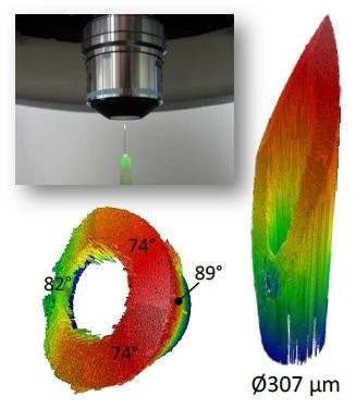
Figure 8. Hypodermic needle measured end-on in a single FOV. Upper left: photograph of setup. Right: obtained data over 1.8-mm scan range. Lower left: same data rotated to show measured slopes up to 89° and automatic identification of bore region.
Conclusion
Thanks to the recent technological progress to improve sensitivity to weak interferometric signals, high-slope and recessed features can be measured through CSI, which was earlier not possible using the technology. Other than improving baseline sensitivity, the technological progress includes tools to further extend dynamic range such as HDR and DNR [6]. As the examples show, measurement of even 89° slopes has now been made possible.
On a general note, the enhancements allow wider latitude in objective selection, and enable operation over larger FOVs for better throughput and at larger working distances for more easy usage.
Acknowledgments
The original work presented in this paper benefited from key contributions and input from Eric Felkel, Nate Gilfoy, Mackenzie Massey and Dan Russano.
References
[1] de Groot P. Coherence Scanning Interferometry. In: Leach R, editor. Optical Measurement of Surface Topography. Berlin: Springer Verlag; 2011. p. 187- 208.
[2] ISO, [25178-604:2013(E): Geometrical product specification (GPS) – Surface texture: Areal – Nominal characteristics of non-contact (coherence scanning interferometric microscopy) instruments] International Organization for Standardization, Geneva (2013).
[3] Zygo Corporation, [NexView Optical Profiler], Specification sheet SS-0095 09/12 (2013).
[4] J. Biegen, X. Colonna de Lega and P. de Groot, "Wide-field interference microscopy for areal topography of precision engineered surface," Proc. ASPE annual meeting, paper 4111 (Boston, 2014).
[5] P. J. de Groot, L. L. Deck, J. F. Biegen and C. Koliopoulos "Equal-path interferometer", US Patent 8,045,175 (2011).
[6] Fay, M. F., Colonna de Lega, X., and de Groot, P. Measuring high-slope and super-smooth optics with high-dynamic-range coherence scanning interferometry. Proc. OSA, 2014: Paper 1981102.
[7] Thanks to Professor Chris Evans and Chris Tyler at the University of North Carolina at Charlotte (Mechanical Engineering and Engineering Science).

This information has been sourced, reviewed and adapted from materials provided by Zygo Corporation
For more information on this source, please visit Zygo Corporation