The exterior and interior surfaces of carbon steel pipes tend to corrode gradually, irrespective of their environment. It is necessary to regularly inspect this corrosion to assess and monitor pipe integrity.
The HydroFORM® corrosion scanner is particularly useful for measuring the remaining wall thickness of pipes. When coupled with a phased array instrument, such as an OmniScan® flaw detector, the HydroFORM scanner provides an efficient way to inspect corrosion as it can give a precise measurement of the remaining material by considering the internal and external surface reflections.
The OmniScan flaw detector examines the ultrasound reflections and measures the delay between the internal and external surface echoes to deliver the remaining wall value at every 1 mm × 1 mm point.
Conversely, in certain situations, inspectors just want to measure the external corrosion, or they have to differentiate between the contribution of internal and external corrosion to the remaining wall value.
Challenge
It is time-consuming and operator dependent when measurements of surfaces are taken manually, such as with a pit gage. The measurement results can differ from one inspection to another and from one user to another. Inspectors require a more reliable technique to inspect quickly and more efficiently. Using lasers to measure external corrosion needs a major investment in training and equipment.
Moreover, laser inspection cannot offer a complete assessment of pipe integrity since it cannot reach the internal surface of the pipe. This drawback means that laser inspection must be backed up by more than one technology or system, which can result in data management, training, and inspection team coordination challenges.
Solution
The HydroFORM scanner is an established solution for checking internal corrosion in pipes. The HydroFORM scanner has a water-column feature that eliminates the need for a wedge and thus offers the advantages of a phased array immersion tank inspection. It provides excellent surface conformance and coupling conditions, even on rough surfaces.
When the HydroFORM scanner is employed with a multigroup instrument, both external corrosion and internal corrosion (remaining wall) can be mapped simultaneously in a single scan. The first group is optimized for internal corrosion, whereas the second group (using the same probe) is optimized for external corrosion mapping.
This offers two distinct C-scans that can be directly analyzed on the OmniScan flaw detector, on a computer with the help of OmniPC™ software, or exported independently in CSV format. For post-processing, spreadsheet software can be subsequently used.
Typical Procedure
The external corrosion mapping procedure is similar to the usual HydroFORM® scanner application but with a few parametric differences.
First, an internal corrosion (remaining wall) group has to be created and this done by setting the law configuration of the first group to “Linear” rather than “Linear at 0°.”0° is the angle of the inspection.
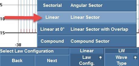
Figure 1. Setting the law configuration to “Linear”
Next, the second group for external corrosion is created by copying the settings for the first group but changing the wedge parameter to “Contact.” This setting allows inspection of the pipe’s outside surface through the water column.

Figure 2. Selecting a “Contact” wedge
The element quantity is set to one element per beam.
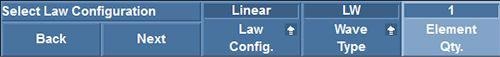
Figure 3. Setting the element quantity per beam to one (1)
The first and last elements have to be set in accordance with the following formulas to guarantee that both groups exhibit the same total aperture and cover the same position on the part:
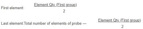
In the following example (Figure 4), four elements were used in the first group, so the first element of the second group was set to 2 elements, and the last element was set to 62 elements.

Figure 4. Setting the first and last element
The focus depth parameter is not pertinent because it is not possible to focus the beam with just one element per beam. For reporting purposes, this parameter is set to unfocused.
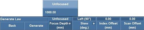
Figure 5. Setting the focus depth to “Unfocused”
It is important to adjust the velocity so that the value for water (1480 m/s, or 0.0583 inches/μs) can be entered. This helps in ensuring the accuracy of the depth values.

Figure 6. Adjusting the wedge delay and velocity
A probe is positioned on the pipe’s corrosion-free area, and the wedge delay is manually adjusted, so the front wall is at 0 mm.
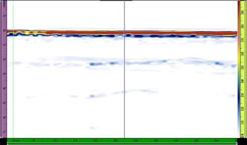
Figure 7. Putting the front wall at 0 mm using wedge delay
- As the surface of the part is only taken into account and ultrasound attenuation in water is marginal, there is no need for time-corrected gain (TCG) on the second group.
- Since gate synchronization cannot be used for the external corrosion group, it is important to have a stable probe holder system, for example, an Evident HydroFORM® and MapROVER™ scanner assembly. Furthermore, an unstable probe holder system could drop in a huge depression on the part, leading to loss of the nominal reference.
- As scan lines cannot be overlapped in linear mode, it is important to note the index delta in the Index End parameter of the Scan>Area menu of the first group (internal corrosion) to accurately set the mechanical index step.
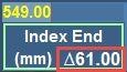
Figure 8. Index delta
Results
Corrosion Data on a Corroded Sample
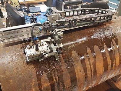
The sample tested was a 20-inch (508 mm) OD pipe with a nominal wall thickness of 0.35 inch (9 mm) with corrosion on the outer and inner surfaces. The scan was done on the circumferential axis on the outside diameter with the help of an assembly comprising of the MapROVER automated scanner and HydroFORM scanner. A resolution of 1 mm × 1 mm covered the surface.
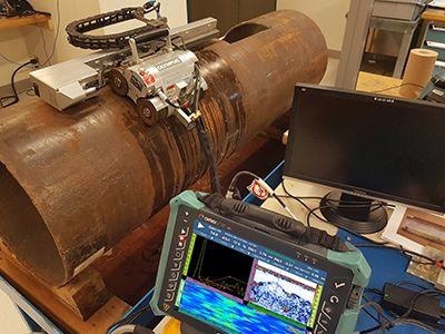
Figure 9. Inspection of a 20-inch pipe
The corrosion was visualized using C-scan and S-scan views. C-scan of the first group (Figure 10) was used to visualize the remaining wall value, considering the internal corrosion. The nominal thickness is represented by the blue color in the C-scan, and the remaining wall becomes thinner as the color progresses from yellow to orange to red. In the C-scan, noncoherent data can be identified in four areas. These areas denote where the external corrosion disrupts the ultrasonic signal.
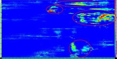
Figure 10. Remaining wall C-scan with signal disrupted by the external corrosion
In the second group, the external corrosion in both the C-scan (Figure 11) and S-scan (Figure 12) can be observed. For this example, which employs a custom color palette (a typical corrosion inspection palette), the redder the color, the deeper the external corrosion. The external corrosion can be easily identified, and it corresponds to the remaining wall C-scan obtained by the first group.
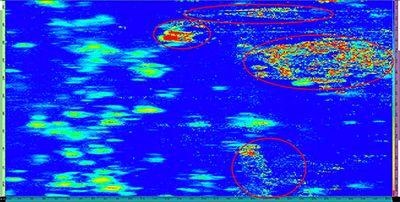
Figure 11. External corrosion C-scan with the HydroFORM scanner
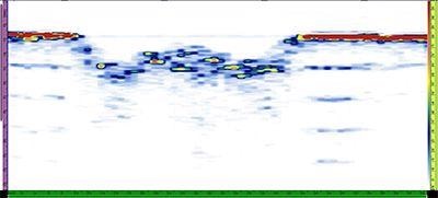
Figure 12. S-scan example of external corrosion acquired with the HydroFORM scanner
Conclusion
With this new inspection procedure which uses the Evident HydroFORM scanner, external corrosion can now be mapped during a typical inspection of the internal/remaining wall corrosion. The OmniScan MX2 flaw detector can be used to create a second group optimized for external corrosion measurement. In addition, internal (remaining wall) and external corrosion data can be exported to a CSV file for further analysis. This technique can reduce the time taken to carry out corrosion inspections and also avoid the investment and training needed when multiple inspection technologies are used.

This information has been sourced, reviewed and adapted from materials provided by Evident Corporation.
For more information on this source, please visit Evident Corporation.