The material and environmental conditions control the dimensional stability of solid bodies. Strains at break should be precisely recorded from a low percentage in the case of metals and around 100% in the case of elastomers and plastics.
Contact extension measurement up to break on flexible and highly elastic specimens like wires or synthetic ropes can pose a major problem. At specimen break, the damaged ends of the specimen whiplash and often hit the specimen’s parts that are still in the grips. Such an effect is induced by elastic resilience. Subsequently, the specimen ends could wrap around the arms of the sensor and impair them. The use of non-contact measurement systems is recommended to achieve safe and precise measurements when testing high elastic, high extension, and contact sensitive materials.
These systems can exactly determine the changes in length, without coming into contact with the specimen at normal temperatures and also at fluctuating temperatures for tests in temperature chambers. Non-contact measurement systems provide a high degree of operational safety for specimen whiplashing at break, thus discharging high mechanical energy, or which unravel at break, for instance, hemp and wire ropes, fiber-reinforced plastics, and elastomers.
The laserXtens stands out from the series of contact-free extensometers as it is a unique development. Since it works without measurement marks, it has absolutely no effect on the specimen.
A technology only offered by Zwick: Non-contact extensometers according to the laser speckle principle.
Advantages of the Non-Contact Measurement Systems
- The specimen behavior is not subjected to any drag force or any effects caused by knife edges. Since the specimen will not be subjected to any force influences, it will not be impaired and fabrication of test results is eliminated
- The systems have an enormously long life-span
- Non-contact extensometers are appropriate for specimens that have a tendency to “whiplash” at specimen break (ropes, wires, elastomers) and also for notch and break-sensitive specimens
- Required accuracy grades of 0.5 and 1 are available
- Any needed gage length can be achieved by applying gage marks at suitable intervals; alternatively, it can be set as needed using a generated (laser speckle pattern, sprayed pattern) or inherent (for example, rebar ribs) pattern
- Biaxial optical measurement can be made
- No thermal bridges when applying temperature chambers, since measurement occurs through a heatable window
Additional Information Through Non-Contact Measuring Systems
Strain Distribution
The option strain distribution is used for determining localized strains, which are subsequently available as channels in testXpert®. In addition, the automatic recognition and evaluation of around 16 measurement marks are possible. The beginning gage length can also be balanced to automatically follow the necking-in in real time (according to ISO 6892-1, annex H).
Test Re-Run
Through the optional Test Re-Run module, an image series can be recorded at the time of a test to be utilized for subsequent recalculation of the strain that has a varied initial gage length (if a number of markings are present). This can be particularly beneficial if local strains have to be assessed at varied locations in component testing, or alternatively, if the necking of the specimen in a regular tensile test took place beyond the original initial gage length. If testXpert® II is used to record the test, then the recalculated strain can be naturally synchronized later with the other measured values. The testXpert® II version 3.4 provides this option.
videoXtens®
Range of Application
videoXtens offers high-resolution, contact-free measurement of extension, both in the compression and tensile direction, on different types of metal, plastic, foils, composites, and rubber. It can also be used for determining R-values according to ISO 10113 and ISO 10275, proof strength (offset yield) in tensile tests according to ISO 6892-1, and transverse strain.
Operating Principle
The digitized image of the specimen, which is processed in real time, is generated by a full-view camera. The gage marks are automatically detected and the displacement of the marks from one frame to another is transformed to an extension value and conveyed to the measurement and control electronics.
Advantages/Features
- The flexible illumination system—that is, Backlight or Frontlight—can be separately adapted for every test task
- Both extensions and optional transverse strain are possible simultaneously. There is no need for separate marking to measure the transverse strain. It is possible to determine the transverse strain at one or more locations. This allows measuring the offset yields in a tensile test in accordance with ISO 6892-1, and also the R-values in accordance with ISO 10275 and ISO 10113
- The videoXtens can also be used for flexure and compression tests
- Measurement range is extremely large and variable, according to the choice of the objective or picture size
- Automatic test mark recognition and acquisition of the initial gage length Le
- Using pattern tracking for preparation-free testing of specimens that have a textured surface; using pattern spray for alternative preparation of specimens that have a homogenous, non-textured surface
- When linked to testXpert® II, the videoXtens’ Video Capturing Plus functionality can be used without any extra hardware. This needs the integration of the image sequence in testXpert® II and also synchronization with the measurement data
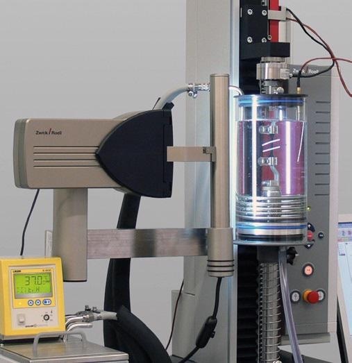
videoXtens—Non-contact measurement in a temperature-controlled fluid bath
Multi-Camera Measuring Systems videoXtensArray
The camera’s field of view decides the resolution of the videoXtens. While smaller image translates to better resolution, the measuring range also tends to be smaller. The Array variant of the videoXtens provides a flexible solution when an application needs a huge measurement displacement integrated with extremely high resolution. Here, a single large field of view is formed by combining the overlapping fields of view from two or more cameras. Markings exiting one camera’s field of view are automatically forwarded to the subsequent camera’s field of view, and so on.
Varied combinations are thus possible, for instance, a pair of cameras in a single videoXtens standard housing, combined with a total field of view, is suitable for the majority of metal tensile tests that have an initial gage length of around 100 mm. A measuring head containing three cameras is provided in an enlarged videoXtens housing. It is especially appropriate for testing wires, structural steel, heavy plates, and a number of plastics. Cameras can also be combined, each in a standard videoXtens housing, to create an array with an extremely large total field of view.
laserXtens® System
Application Range
Extensometers available from the laserXtens system series can be used for measuring deformation or strain on many different materials. The use of the latest laser speckle technology eliminates the need to attach marks and prevents contact with the specimen at the time of the test.
This allows the laserXtens systems to operate in various applications:
- Tests on components
- Compression and tensile tests on plastics and metals
- Tests in temperature chambers
- Deformation measurement on specimens susceptible to whipping on break which could cause damage to a contact-based measuring system
- Tests on specimens where contact is not possible or undesirable owing to the condition or properties of the specimen
- Applications where non-contact biaxial strain measurement is required
Flexible yet easy to operate, the laserXtens systems provide the perfect solution for quality control applications and, at the same time, offer key technological advantages to organizations involved in research and development.
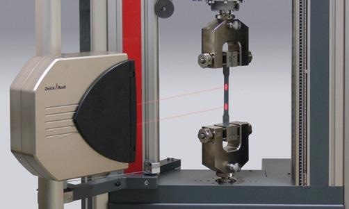
Function Description
The laserXtens systems include measuring heads comprising of a laser light source and digital cameras. When the specimen is illuminated with the laser light, a speckle pattern is produced on the test specimen’s surface.
The speckle pattern can be considered as a “digital fingerprint” or “virtual measuring mark” on the specimen’s surface and is tracked with the two full-frame digital cameras. This virtual measuring mark is tracked by the laserXtens software in consecutive images captured at the time of the test, and this process is known as speckle tracking.
When a load is applied to the specimen through the testing machine, the speckle pattern shifts and the laserXtens software iteratively tracks the speckle pattern from one image to another in real time and establishes the strain in the specimen.
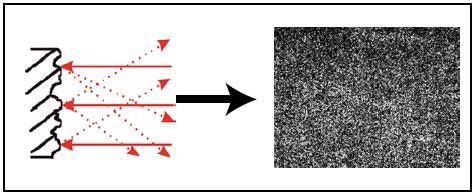
A speckle pattern is generated on the surface of the specimen with the laser light
Each camera image is shown in an analysis window on the PC and yellow cross hair lines define the gage length. For the optional measurement of transverse strain, the transverse measurement systems can be set up using the available crosshairs.
Types
- laserXtens Array — A single measuring head fitted with four fixed cameras. The cameras’ fields of view are integrated to form a single large image
- laserXtens and laserXtens HP — The measuring head includes a pair of cameras placed on motorized slides, making it possible to change the spacing between the cameras and thus set varied initial gage lengths
- laserXtens Compact and laserXtens Compact HP — Single-camera systems designed for small to micro specimens
Advantages/Features of the laserXtens Systems
- The laserXtens systems integrate high precision for micro, normal and large specimens
- The laserXtens systems do not make any contact with the specimen and there is no effect on the test caused by the laser light
- Specimen markings are not required, resulting in a number of benefits:
- Saves time — particularly for high specimen throughput
- Can be used in a high-temperature furnace and temperature chambers
- Enables simple use in automated systems, since manual specimen preparation is not required
- The laserXtens, unlike conventional contacting extensometer, is capable of measuring strain with a high level of accuracy on short specimens that have gage lengths down to 1.5 mm
- The laserXtens systems are fully incorporated into the testXpert® II application software. For a parallel view of testXpert® and laserXtens live picture, a second monitor is recommended
laserXtens®
Types
It is possible to mount the laserXtens at varied distances to the specimen, thus making it appropriate for use with temperature chambers, for instance. When mounted close to the specimen, the laserXtens HP becomes suitable for strain-controlled tests in accordance with ISO 6892-1 method A1closed loop.
Function Description
Two modes of operation are included in the software algorithm. As the virtual marks shift inside the camera’s field of view, the software automatically shifts the analysis window. In this mode, an elongation of typically 40 mm can be determined. When the analysis window arrives at the edge of the field of view, there is an automatic switch to the second measuring mode.
The material flow inside the analysis windows is now determined and the strain value is calculated accordingly. Based on material and specimen’s behavior, this mode results in highly accurate measurements (class 1), even being not according to the standard.
After the extensometer is securely and mechanically linked to the testing machine, it follows the cross-head at half the test speed. This guarantees that the laserXtens remains invariably in the center of the test area, and consequently, the effective measuring range for speckle tracking is augmented.
Advantages/Features
- The resolution is 0.15 μm (0.11 μm for laserXtens HP)
- The laserXtens HP can be applied to strain-controlled tests to ISO 6892-1 method A1 closed loop; appropriate for gage lengths of ≥50 mm
- The laserXtens meets or surpasses class 1 (0.5 for laserXtens HP) of ISO 9513 (class B2 of ASTM E83)
- The laserXtens can even be used for concurrent measurements of axial strain and torsion
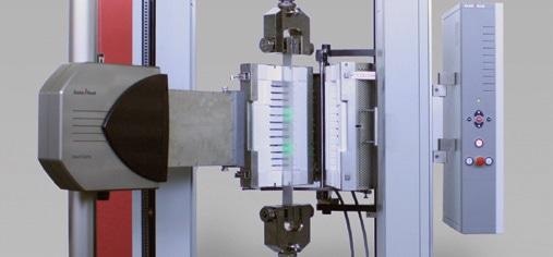
Figure 1. Equipped with green laser light and high-temperature tunnels the laserXtens can also be used for high temperature testing up to 1000 °C.
laserXtens Compact
Range of Application
The single-camera measuring systems are specifically suitable for testing small to micro specimens. Alternatively, the laserXtens can also work with just a single camera head. Both analysis windows, in this configuration, are set within the one camera image and the gage length is indicated by the distance between the analysis windows. Therefore, the gage length is restricted to the size of the camera’s field of view.
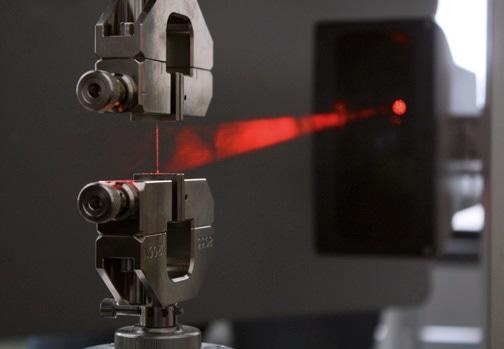
Figure 2. laserXtens Compact
Types
The laserXtens Compact is compatible with all Allround-Line floor and table-top testing machines, while the laserXtens Compact HP has been developed for mounting on the Precision Line Vario.
Advantages/Features
- The resolution is 0.15 μm (0.04 μm for laserXtens Compact HP on PrecisionLine Vario)
- The laserXtens Compact meets or surpasses 0.5 of ISO 9513 (class B2 of ASTM E83)
- The laserXtens Compact can also be used for biaxial testing. It determines transverse strain without the necessity to attach extra specimen marks on specimens.
laserXtens Array
Range of Application
The laserXtens Array measuring head includes four fixed high-resolution cameras, unlike the regular laserXtens, on which a pair of digital cameras placed on motorized slides can be applied to set varied initial gage lengths.
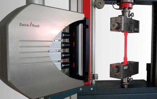
Figure 3. laserXtens Array with four cameras
Function Description
A single, large image is formed by combining the overlapping fields of view of the four cameras. Here also, the two virtual gage marks are followed at the time of the loading process (speckle tracking). When a gage mark meets the edge of the field of view of one camera, it is forwarded to the field of view of the neighboring camera. This technique considerably expands the measuring range.
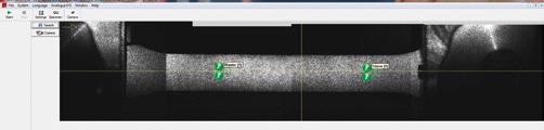
Figure 4. Complete specimen image assembled from four images
The system moves to flow mode only when one of the gage marks arrives at the edge of the total field of view. In flow mode, the material flow below the evaluation window is measured to determine the calculated value. In addition, based on the material and/or the specimen deformation, excellent results (that is, accuracy grade 1) are achieved with this non-standard technique.
Advantages/Features
- The resolution is 0.15 μm
- The laserXtens Array is characterized by an extremely large measuring range
- The laserXtens Array does not have any moving parts and is fully maintenance free
- The laserXtens Array conforms to class 1 of ISO9513 (class B2 of ASTM E83)
- Different gage lengths can be set very quickly
- The laserXtens Array can also obtain transverse strain without any extra markings; biaxial measuring can also be achieved
- As an option, the extensometer can also be expanded into a laserXtens Array/videoXtens hybrid system
- With an additional camera for transverse strain measurement, it becomes subsequently possible to establish the R-values in accordance with ISO 10275 and ISO 10113, for instance
lightXtens®
Range of Application
lightXtens® is an optical extensometer and is suitable for providing accurate and reliable measurements in tensile tests on highly elastic, highly ductile, and touch-sensitive materials like latex, elastomers, as well as all types of foil.
It is appropriate for all specimens exhibiting whiplash or high energy at break and is thus likely to affect mechanical, contact-measuring systems. This is usually the case with ropes, belts, and steel litz wire, for instance.
It offers accurate, non-contact strain measurement, even over long temperature ranges in temperature chambers. lightXtens provides an attractive alternative to video or laser-based extensometers, thanks to its user-friendly operation and robustness in test conditions.
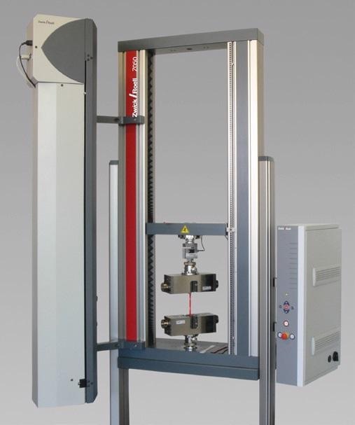
Figure 5. lightXtens
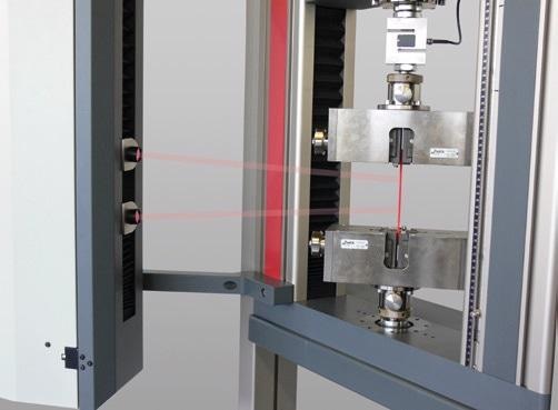
Figure 6. lightXtens identifies gage marks automatically
Advantages/Features
- Non-contact operation — ideal for compression and tensile tests
- Can be used over a long temperature range when used along with temperature chambers, since altering between raised and ambient temperature does not need any exclusive set-up operations
- Automatic gage mark recognition
- Connection to testControl electronics is enabled through a digital bus system, with synchronized force-travel measurement
- Meets Accuracy Class 1 to ISO 9513 from 3 mm
- Low-maintenance, wear-free operation
- Initial gage length is automatically determined at the time of the test and conveyed to testXpert® II
- lightXtens can be easily operated:
- Simple specimen preparation through automatic or manual marking devices
- Optics do not have to be adjusted or configured
- Impervious to fluctuating environmental conditions like extraneous light
- Fully automatic test sequence (such as attachment, automatic positioning of extensometer at the start location, and automatic determination of initial gage length)

This information has been sourced, reviewed and adapted from materials provided by ZwickRoell GmbH Co. KG.
For more information on this source, please visit ZwickRoell GmbH Co. KG