The growing calls for lower weight carbon fiber composites in automotive applications is propelling the carbon fiber industry towards the development of high quality inexpensive carbon fiber. Most carbon fiber produced today uses PAN as the precursor which is not helpful in producing an inexpensive carbon fiber.
Other precursor options, such as lignin, have been explored in the production of carbon fiber for more than forty-five years with only partial success. A few of the main obstacles include how to process material that is not able to support its own weight through most of the thermal process step; melt-spinning the amounts of precursor required to feed a production plant; and the resulting modulus, strength, and brittleness of the carbon fiber produced.
Pitch precursors are regaining in popularity as process and mechanical technology has progressed and since pitch precursors contain up to 85% carbon and are not required to be stabilized as greatly as PAN. This could result in a cheaper carbon fiber.
This article outlines the steps required to turn a pitch precursor into carbon fiber and the vital aspects and inherent hardships associated with these steps.
Corporate Average Fuel Economy is mandated to grow to 22.3 km/L (52.5 mpg) by 2025. One method that automobile manufacturers will use to achieve this mandate is through utilizing lightweight materials such as carbon fiber. If three major automobile manufacturers such as GM, VW, and Ford were to use 8.2 kg of carbon fiber in each vehicle they manufacture, worldwide carbon fiber production capacity would, at the very least, need to double.
It is expected that to become feasible for the automotive market, the cost of carbon fiber will have to be cut in half. Cheaper precursors are one way to cut the price of carbon fiber.
Comparison to Current Automotive Materials
To comprehend the effect that possible demand from the automotive industry could have on the carbon fiber production industry, it is useful to understand the volumes of conventional materials that are used by the global automotive industry. In the automotive industry, aluminum and magnesium are the most rapidly growing materials because of their light weight and they are being used more and more in manufacturing car components, power train, body structures, etc. [1].
In 2018, 86 million vehicles were sold worldwide[2] with the average weight being 1815 kg[3]. Using a moderate estimate that half [4] of an average vehicle is constructed from some kind of metal, then the consumption of metals by the automotive industry is more than 78,000,000 Metric Tons.
When compared against the 2018 global capacity for carbon fiber production, which is approximately 149,000 Metric Tons[5] it becomes apparent that for carbon fiber to become a commonplace material in the automotive industry its’ manufacturing capacity must increase drastically.
Increasing the world’s carbon fiber capacity is not the only major obstacle that must be taken into account; it is also the $/kg CF in comparison with aluminum and steel. Now, 50k industrial grade fiber can be obtained for $15 - $18/kg[6]. The present cost for low carbon steel coil is $1.10/kg [7] and the average cost of recycled aluminum in 2018 was $2.27/kg [8]. Figure 1 demonstrates these differences in cost.
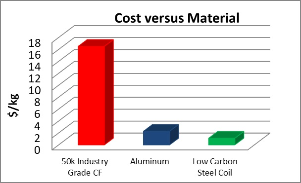
Figure 1: Aluminum and Steel cost/kg compared to carbon fiber cost/kg. Image Credit: Harper International
The challenge of reducing the cost per kilogram has increased pressure in the development of “low cost carbon fiber”, with many research groups racing to be the first past the finish line. One big possibility, in order to develop cheaper carbon fiber, is to use an inexpensive precursor such as pitch.
Brief Background on Carbon Fiber
In the 1950s, carbon fibers were first developed as reinforcement for high-temperature components on missiles. These initial fibers were produced by heating strands of rayon until they carbonized. In the 1960s, as the carbon yield was only around 20%, and the resulting fibers had low stiffness and strength properties, , polyacrylonitrile (PAN) was designed as a precursor for carbon fiber. Yielding about 55% carbon, this raw material had substantially improved mechanical properties than fiber derived from Rayon.
During the 1970s work continued to find other raw materials which resulted in the introduction of carbon fibers made from a petroleum pitch, derived from oil processing. Yielding about 85% carbon, these precursors had modulus and strength that was regarded as acceptable for many applications. Due to the outstanding flexural modulus and ability to be easily graphitized, pitch fibers were considered an exceptional choice for specialty applications.
PAN versus Pitch Carbon Fiber
The following discusses a few of the differences between a Pitch based carbon fiber and a PAN based carbon fiber and their processes.
The most common kind of carbon-fiber, PAN based carbon fiber makes up 90% of carbon fiber manufactured. It has a carbon fiber conversion yield is 50 to 55% and it is predominantly chosen for structural reinforcement because of its intermediate modulus and high tensile strength. Pitch is a polycyclic aromatic hydrocarbon drawn from petroleum asphalt, coal tar or polyvinyl chloride. It has a carbon fiber conversion yield ~80% or greater and can reach a considerably higher modulus in comparison with PAN, and has greater electrical and thermal conductivity.
PAN based carbon fiber lines need substantially greater abatement systems compared to Pitch due to their substantially lower carbon yield. The off-gases being treated are also substantially different from PAN to Pitch and this also impacts the abatement system. The greatest difference in exhaust off-gas constituents between PAN and Pitch is HCN; the pitch carbon fiber process does not release any detectable HCN. The main constituents of the exhaust off-gas for Pitch are CO, CO2 and H2, and for PAN are HCN, NH3, CO, CO2 and H2. Some tars and chars are produced by both processes.
Sulfur is the main residual that is usually in a Pitch carbon fiber and occurs naturally; for PAN carbon fiber, sulfur is only a residual if DMSO is used as a solvent and the sulfur is not sufficiently removed in the desulfurization stage during spinning. Sulfur is not desired in the PAN as it can lead to metal dusting and corrosion in both the high and low temperature furnaces. The sulfur in the pitch is not likely to be an issue until extremely high temperatures (>2500°C) so is much less problematic for the equipment.
Another problematic residual that can be in PAN is sodium from utilizing sodium thiocyanate as a solvent in the spinning process. Sodium residual is undesirable as it can react in the high temperature furnace to form toxic Sodium Cyanide. For both precursors, it is vital to comprehend what residuals from the spinning process can come out during the thermal treatment stages and related reaction kinetics to be able to select the right construction materials and be prepared in the design for potential issues that could arise, such as buildups in difficult to reach places.
Finally, in relation to what is physically coming off the fiber during thermal treatment, another notable difference between Pitch and PAN is the number of particulates generated. In contrast to Pitch, which has limited particulates coming off the fiber, the sizing on the PAN fibers produces a notable number of particulates that must be dealt with and can need an extra piece of capital equipment such as a baghouse at the exhaust stack to trap these particulates. Buildup of these particulates inside the exhaust pipes and equipment may generate uniformity issues and increased maintenance downtime if not appropriately managed during the design phase.
For PAN based carbon fiber to reach its highest possible modulus, a further thermal processing step is needed that uses an ultrahigh temperature furnace. This furnace is costly due to the construction materials and maintenance because of its high temperature which leads to the internal components wearing much more rapidly, particularly the heating elements. Pitch can reach a greater modulus than PAN without this extra step because it begins more ordered than PAN.
For PAN to acquire its mechanical properties, unlike Pitch, it must be stretched through stabilization and carbonization. This stretching introduces extra pieces of capital equipment (tension stands) and depending on the country where these pieces of equipment originated; a special export license will probably be necessary. Because it is not possible to stretch Pitch its properties are determined during the spinning process.
PAN can support a great deal more than its own weight through the full process so during processing supporting the fiber is not required. Usually PAN is spun into fibers and put on spools that are then unwound and pulled into the stabilization oven with tension stands. The range of filament count is big with tows from 1k to 600k and though the PAN spinning process is difficult to master, is well known and presently utilized for large scale production.
Pitch cannot support its own weight through the full process, so support for the fiber is required during processing. Frequently Pitch is spun directly onto the belt that is then fed into the stabilization oven. The usual format is a nonwoven mat versus tows for PAN, and for Pitch tows, the range of filament count is tiny compared to PAN, typically <2k. The purification process of the Pitch and the spinning process are very difficult to master in comparison with PAN and is not well understood or applied at a large scale.
Table 1 lists a few of the properties for commercially available PAN and Pitch based carbon fibers and demonstrates the variations in mechanical properties, especially the modulus.
Table 1. Mechanical properties of various carbon fibers on the market. Source: Harper International
| Precursor |
Name |
Mfr. |
Tensile Modulus (GPa) |
Tensile Strength (GPa) |
| PAN |
TC55 |
Formosa |
380 |
4.4 |
| HM63 |
Hexcel |
438 |
4.8 |
| M55J |
Toray |
538 |
4.0 |
| M60JB |
Toray |
588 |
3.8 |
| Pitch |
K1392U |
Mitsubishi |
759 |
3.7 |
| K800 |
Amoco |
863 |
2.1 |
| K13C2U |
Mitsubishi |
897 |
3.8 |
| K1100 |
Amoco |
932 |
3.2 |
| K13D2U |
Mitsubishi |
966 |
4.0 |
Pitch Precursors
Pitch is a polycyclic aromatic hydrocarbon obtained from petroleum asphalt, polyvinyl chloride or coal tar. It is comparatively inexpensive compared to PAN and has a notable higher carbon fiber yield. There are two kinds of pitch, Isotropic and Anisotropic (mesophase) but all pitch begins as Isotropic and it is through processing that the pitch becomes a Mesophase. The two resultant carbon fibers differ in their structure, properties and nanotexture [9]
Isotropic pitch type carbon fiber is typically a discontinuous fiber (chopped) of 12 – 18mm in diameter with 1.6 g/cm3 of density and has low modulus, 40 GPa, and low thermal conductivity because of its weak structural orientation of carbon atoms and underdeveloped graphite crystallinity. With its competitive cost, Isotropic Pitch Type Carbon Fiber is extensively applied for industrial uses due to light weight, heat resistance, chemical stability and abrasion characteristic.
Mesophase pitch type carbon fiber is usually a continuous fiber (~2k filaments) or sprayed as a nonwoven mat with filament diameters of 7 - 10mm and density of 1.7 - 2.2 g/cm3 that results in a large range of modulus from ~600 GPa to ~965 GPa[10]. Most carbon fiber made from pitch is uses mesophase pitch because it is possible to achieve a high degree of orientation of the hexagonal layers along the fiber axis during spinning so that stretching during the thermal processing is not necessary [11]. This highly orientated molecular structure and high crystallinity may result in a carbon fiber with a much greater modulus than traditional PAN fibers and can come close to the theoretical limit of 1000GPa.
Processing Pitch into Carbon Fiber
The process for making carbon fibers is part mechanical and part chemical. Figure 2 below is a schematic of the CF process for nonwoven mats from the pitch precursor through the resulting carbonization furnace. The schematic illustrates solvated mesophase pitch spun into fibers in a melt blown device. This schematic demonstrates the required spinning system’s complexity in comparison to the remaining processing equipment. This spinning system’s main components include a pitch feeding device, vacuum vent, extruder, spinning pump, ballast pump, spinneret head, filter, air flow jet regulator, fiber collector, temperature and pressure system, and a vacuum control system required to form the needed precursor format before stabilization and carbonization that results in the final carbon fiber product.[12]
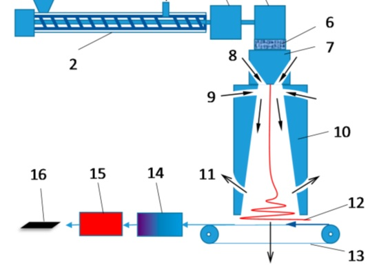
Figure 2: A schematic diagram of a melt blown fiber spinning apparatus and thermal processes for manufacturing pitch-based CFs. [1-pitch feeding; 2-extruder; 3-exhaust vent; 4-ballast pump; 5-spinning pump; 6-filter; 7-spinneret head; 8-primary air stream; 9-secondary air stream; 10-diffuser; 11-air exhaust; 12-spun fiber web; 13-moving belt collector; 14-stabilization oven; 15-carbonization furnace; resulting 16-CF web.] Image Credit: Harper International
Figure 2 is a simple view and several cases a schematic like this is used as a shining example to show how easy it is to make carbon fiber from pan, pitch or other precursors. The commercial side says “buy this amazing precursor from us and it’s up to you the customer to process it into carbon fiber but see how easy it is” as they point to this figure. Industry figures, however, know that changing any precursor into carbon fiber is much more complex and capital intensive than what Figure 2 illustrates.
Figure 3 shows what is actually entailed and is a schematic of a 4.0 meter wide ‘Pilot’ System for processing a pitch mat. This schematic has been simplified, is specific to one individual process and is not a satisfying solution for all kinds of pitch precursor or process. The schematic’s aim is to illustrate the size of the equipment required for a Production scale plant. Note the ‘operator’ figures (1.8m tall) throughout the schematic for a reference to the actual equipment size. In contrast, Photo 1 is a Harper 4.0 meter ‘Pilot’ scale system).
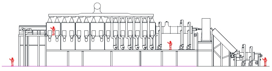
Figure 3: Harper International 4 meter wide Pitch Thermal Processing ‘Pilot’ Plant. Image Credit: Harper International
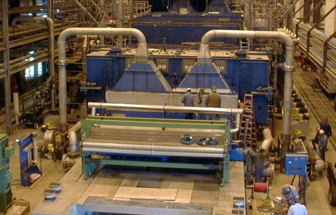
Photo 1: Harper International 4 meter wide Pitch Thermal Processing ‘Pilot’ Plant. Image Credit: Harper International
The following sections outline the process from spinning through surface treatment and the complexities and challenges which are intrinsic in this process.
Spinning
Isotropic Pitch is heated at high temperature then filtered and treated in nitrogen, based on the needed client recipe, for a fixed number of hours to prepare a carbon fiber precursor with the needed softening point temperature. This step is vital in order to successfully spin the fiber and will determine whether the resulting pitch is mesophase or isotropic. The resultant pitch precursor is then melt-blown or melt-spun into fibers through a circular nozzle spinneret.
Mesophase pitch can be melt spun, but due to its flow characteristics the process can be hard and solvents may be required which then must be removed. This is known as solvated mesophase pitch and unlike traditional mesophase pitch, solvated mesophase pitch usually consists of more than 70% by volume optical anisotropy. Adding solvents ensures the pitch is more spinnable at reduced temperatures. [12, 13, 14, 15]
Devolatilization and Stabilization
The stabilizing chemical reactions are complicated and entail a number of steps, some of which can happen at the same time. This step is used so that the fibers are cross-linked to the point where, during the carbonization, they cannot be melted or fused together.
For solvated mesophase precursor, a critical area to be considered is the devolatilization of the precursor which requires a controlled, recirculated atmosphere with solvent recovery. The length of the devolatilization section is notable with many zones of control. Consistent temperature control within a zone, as well as the rate at which the fiber is heated, is vital to fiber treatment. The size and number of the zones is chosen based on a comparison of ideal zone length against the cost per zone of independent control.
Carbonization
When the fibers are stabilized, they are heated for several minutes to high temperatures (>1250°C) in a furnace with an inert atmosphere. As the fibers are heated, they start to lose their non-carbon atoms. As these atoms are lost, the left over carbon atoms form tightly bonded carbon crystals that are aligned almost parallel to the long axis of the fiber.
Discussion
Processing alternate precursors poses technical challenges that vary from PAN precursors. To be successful, it is vital to have a thoroughly developed and well understood process and the appropriate thermal and material handling equipment to match the individual needs of each customer’s precursor.
Highly customized, pioneering equipment will be required from small-scale to massive commercial plants. As production rates skyrocket, so does the effect of downtime on production cost. Stable processes will be required in order to prevent downtime and successfully profit. In particular, this means equipment with advanced thermal and atmosphere flow uniformity as well as strong material handling systems will be needed.
PAN technology is inappropriate if an alternate precursor (in a mat or tow format) cannot support its own weight. Harper can provide thermal processing equipment wherein the material is supported. However, this is where a “sanity check” must be conducted on how to continue . At research scale, should the equipment be continuous or batch? Even small batch equipment can be complicated and costly and the program should take into account the reality of the time it can take to scale up the spinning process.
Consideration should be used for what equipment is actually necessary to be able to measure success and this is the usually the stabilization oven. It is likely a continuous carbonization furnace is not required at this stage until the program has progressed to spinning and laying down material in substantial amounts and quality. Harper will partner with a client to help them determine and develop their requirements.
References
[1] Automotive Metal Market Analysis By Product (Aluminum, Steel, Magnesium), By Application (Body Structure,Power Train, Suspension), By End-use, And Segment Forecasts, 2018 – 2025, Grand View Research, Published Aug. 2017.
[2] http://carsalesbase.com/global-car-sales-2018/
[3] https://www.autolist.com/guides/average-weight-of-car
[4] https://www.forbes.com/sites/greatspeculations/2015/05/20/trends-in-steel-usage-in-the-automotive-industry/ #136209e51476
[5] https://www.statista.com/statistics/380549/leading-countries-by-carbon-fiber-production-capacity/
[6] https://www.compositesworld.com/columns/autocomposites-and-the-myth-of-5lb-carbon-fiber
[7] https://agmetalminer.com/metal-prices/carbon-steel/
[8] https://firstquarterfinance.com/wl-r-price-aluminum-per-pound-everything-else-know-recycling-aluminum/
[9] “Engineering and Applications of Carbon Materials”, Michio Inagaki, Feiyu Kang, in Materials Science and Engineering of Carbon: Fundamentals (Second Edition), 2014
[10] “Carbon Fiber”, http://www.formula1-dictionary.net/carbon_fiber.html
[11] “Carbon Fibers”, Michio Inagaki, in New Carbons - Control of Structure and Functions, 2000
[12] “Meltblown Solvated Mesophase Pitch-Based Carbon Fibers: Fiber Evolution and Characteristics”, Zhongren Yue, Chang Liu and Ahmad Vakili in Journal of Carbon Research. C 2017, 3 (26).
[13] Walter, M.; Kalback, H.; Romine, E.; Bourrat, X.M. Solvated Mesophase Pitches. U.S. Patent 5,259,947, 9 November 1993.
[14] Southard, W.M.; Romine, H.E.; Nanni, E.J.; Carel, M.W. Process for Making Solvated Mesophase Pitch. U.S. Patent 5,437,780, 1 August 1995.
[15] “Solvated mesophase pitch-based carbon fibers: Thermal-oxidative stabilization of the spun fiber”, Yue, Z.; Liu, C.; Vakili, A. in J. Mater. Sci. 2017, 52, 8176–8187.
[16] "Mesophase pitch and its carbon fibers", Matsumoto T. in Pure and Applied Chemistry. 57 (11): 1553–1562 (1995).
[17] “Effect of Liquid Crystalline Texture of Mesophase Pitches on the Structure and Property of Large-Diameter Carbon Fibers”, Guanming Yuan, Baoliu Li, Xuanke Li, Zhijun Dong, Wanjing Hu, Aidan Westwood, Ye Cong, and Jiang Zhang in ACS Omega 2019, 4, 1095-1102
Acknowledgments
Produced from materials originally authored by Dr. Renee Bagwell from Harper International.

This information has been sourced, reviewed and adapted from materials provided by Harper International.
For more information on this source, please visit Harper International.