Certain electromagnetic devices such as differential transformers are effective at translating the displacement of a magnetic armature into an AC voltage, which is a linear function of the displacement.
They are mainly composed of primary and secondary coils that wind around an air core and an adjustable armature is used to regulate the electrical coupling between them.
A basic winding setup is exhibited in Figure 1, which demonstrates the configuration of a three coil winding type.
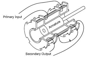
Figure 1. Three Coil Configuration. Image Credit: Columbia Research Laboratories
While analysis of each type is mostly similar, they can vary via the maximizing or minimizing of specific parameters. When an AC source is used to energize the primary coils, this provokes voltages in the two secondary coils.
The secondary windings are typically connected in series bucking with the mains so that the transducer output is the vector difference of the two voltages induced in the secondaries. The output voltage approaches zero at null.
When displacing the core from null, the voltage induced in the coil which the core moves towards increases. There is a decrease in voltage in the opposite coil resulting in a differential voltage output from the transformer, which can be designed to control linearity with core motion.
The output goes through a phase reversal when passing through the null. Figure 2 displays output voltage vs. displacement with phase reversal shown as voltage polarity.
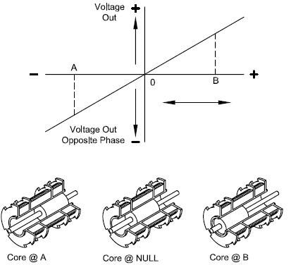
Figure 2. Output Voltage and Phase vs. Displacement. Image Credit: Columbia Research Laboratories
Differential Transformer Characteristics
Linearity and Linear Range
The output voltage of a differential transformer is determined as a linear function of core displacement within a limited range. The characteristics start to deviate from a straight line when this range is exceeded.
The degree of linearity within the linear range can be said to be the output curve’s maximum deviation from the straight line of best fit passing through the point of origin, which is classified as the percentage of output at the nominal range.
Generally, the linearity and linear range are specified for a given resistive load.
As the output impedance of a differential transformer is comparatively constant, the output loading will not adversely impact linearity, although it will cause changes in sensitivity and phase shift.
Sensitivity and Output
The rated sensitivity is typically stated in terms of millivolts output per thousandths of an inch core displacement per volt input (frequently written as mV output/0.001” core displacement//v input.).
Since there is a variation in voltage sensitivity, in accordance with frequency, excluding some designs over a limited frequency range, the frequency should be determined when specifying sensitivity.
The actual output voltage for a given core displacement can be established by multiplying the sensitivity by the displacement in thousandths of an inch, then again multiplying the result by the input voltage.
The differential transformer is not unlike a conventional transformer in a number of its output characteristics. At low frequencies, its output impedance is approximately resistive, while at higher frequencies, it may take on high reactive values.
Therefore, there is usually an increase in sensitivity and output relative to frequency, particularly in the low-frequency portion of the range specified for a particular differential transformer. However, the sensitivity at the higher frequencies is appreciably impacted by the load because as the frequency increases, so does the output impedance of the transformer.
Theory and Applications of Linear Variable Differential Transformers
Resolution
The output voltage variation of a differential transformer is stepless. Therefore, the effective resolution is completely contingent on the minimum voltage or current increment, which can be detected by the associated measuring system.
Excitation
The basic inductive arrangement of the differential transformer with a movable magnetic core can be developed for operation at any AC frequency in the range from 60 cps to 20,000 cps.
When using the transformer to measure static displacement or to detect linear motion, which is not inclusive of oscillatory components approximately above 6 cps, the common 60 cps power frequency is usually suitable. The 400 cps aircraft power frequency is used extensively and is appropriate for a number of applications.
Accurate response to vibration and rapid mechanical movement necessitates the use of an excitation frequency at least 10x the most appropriate frequency present as an element of the mechanical motion, or preferably higher.
The excitation power needed to generate useful sensitivity in various transformer types vary with transducer size and application.
In a number of applications, this power is only a fraction of a watt. In practice, this power is typically restricted by the maximum hot spot temperature produced within the primary winding that is exposed to the maximum ambient temperature conditions of the specific application.
As a result of the greater reluctance of the magnetic path, core saturation does not usually occur with any current value that does not ultimately overheat the primary winding. When excitation of a differential transformer occurs at a fixed voltage, the primary current will vary downward as frequency increases.
Since the heating affect is relative to the square of the current of all practical purposes, an increase of the maximum input voltage by the necessary amount is possible at higher frequencies to preserve the primary current at a fixed value, only restricted by the maximum absolute voltage of the winding and circuit insulation.
A constant current power source rather than a constant voltage source is preferable for accurate operation, especially when using an input level that generates a substantial temperature rise in the transformer.
A constant current source eradicates any output variation directly as a result of the basic primary resistance variation with temperature. This primary resistance variation is crucial at low frequencies but might be inconsequential at higher frequencies where the primary impedance is highly inductive.
Therefore, it is clear to see that a differential transformer should be used with a voltage source across a wide temperature range, and it is advisable that a high frequency carrier be employed for optimal temperature stability.
Variations in Differential Transformer Characteristics Due to External Variables
Fluctuations of input Voltage and Frequency
Fluctuations in the input voltage of a differential transformer are contemplated as a relative proportional fluctuation of its output voltage. Therefore, to reduce the potential of error that results from fluctuation in the source voltage, a regulating device should be employed.
Equal considerations of such factors that apply to the fluctuation of input voltage are also relative to input frequency fluctuation. Generally, percent changes in frequency yield smaller percent changes in sensitivity that would lead to fluctuations in the input voltage.
Displacement Measurement
Employing LVDT to sense and display linear motions necessitate the use of auxiliary electronic instruments. The most basic arrangement, which offers minimal accuracy, would need an AC excitation source of suitable amplitude and frequency to supply the primary winding of the LVDT and a high‐impedance AC voltmeter tracking the secondary output voltage.
This arrangement would suggest a voltage proportional to the core positions. Since the voltmeter can signify only voltage levels, no directional sense would be necessary.
Thus, it is necessary to employ a “demodulator” to produce a bi‐polar output relative to linear displacement around the null position. The demodulator has the capacity to electronically transform the AC output signal from the LVDT to a variable DC voltage which is an analog representation of the core position.
This DC voltage fluctuates in from a maximum positive value at the maximum “positive” displacement from the core, through to zero voltage at the null position, to a absolute negative voltage at the maximum “negative” displacement.
Positive displacement is fundamentally determined as a core movement from null toward the lead‐wire end of the LVDT body. The most straightforward form of bi‐polar demodulation is comprised of two half‐wave rectifiers, one of each secondary winding, with the common secondary lead or leads returning to the mid‐point of the output filter capacitors.
The output signal becomes the algebraic sum of the two signals that were rectified, as shown in Fig. 3(a). Fig. 3(b) displays a complete wave version of the demodulation method. The circuit of Figure 3(b) is rarely put into action because of its additional complexing and higher rectification losses.
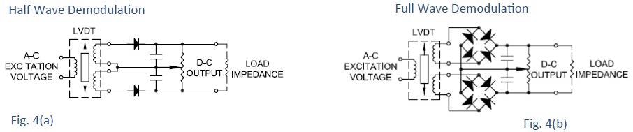
Figure 3. Demodulators‐Direction Sensitive. Image Credit: Columbia Research Laboratories
Below are some of the advantages of this method:
- The direction sense of core motion is preserved by the output
- The circuits are comparatively simple
- In view of the fact that recertification of each secondary output takes place the diodes typically operate beyond the threshold level and do not introduce non‐linearities.
- Phase Shifts do not appreciably affect the linearity
The following list presents some of the disadvantages of this method.
- In order to preserve the whole circuit’s symmetry, the load must be balanced or ungrounded.
- Mixing two secondary rectified outputs into one DC output which is based on the resistance mixing principle, results in large output power losses
- Due to space-saving requirements in certain LVDTs, the output of each secondary at the end of the travel range may be considerably lower than the threshold level of the diode. In this instance, non‐linearity will be introduced into the DC output. Such demodulator techniques are extensively employed with LVDTs in that they yield excellent results when operated with unconventional transformers.
Synchronous Demodulators
To circumvent any restrictions impeded by the simple diode rectifier, the synchronous or phase‐sensitive demodulator is typically used with LVDT and similar AC-operated transducers. These circuits use the fundamental principal of phase detectors, synchronous demodulators and phase comparators.
This is based on the idea of correcting a difference voltage that was artificially created instead of the signal itself. Since the diodes are used to correct the difference signals by appropriate selection of the referenced voltage, the amendment occurs at voltage values far exceeding the threshold of the diodes.
The conventional circuit utilizing this principle is displayed in Fig. 4.
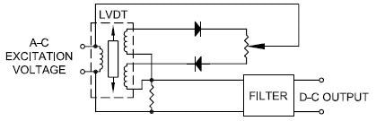
Figure 4. Demodulators. Image Credit: Columbia Research Laboratories
However, one downside to this demodulator is that it is sensitive not only to amplitude changes but also to phase variations of the signal versus the reference voltage. This may result in an adverse decline in performance when used in parallel with particular differential transformers, especially those designed for long travel.
A variety of methods have been developed to circumvent the issues introduced by LVDT phase shifts. For absolute convenience, an instrument that pairs an AC excitation source with an output signal demodulator is usually employed.
These instruments may utilize simple diode demodulators or intricate synchronicity with the potential for phase shift compensation. Furthermore, gain or normalization controls are often built into these instruments.

This information has been sourced, reviewed and adapted from materials provided by Columbia Research Laboratories, Inc.
For more information on this source, please visit Columbia Research Laboratories, Inc.