Introduction The gamma prime (γ’) strengthened IN738 superalloy is extensively used in hot sections of aero-engines and power generation turbines due to its excellent elevated temperature strength and hot corrosion resistance. The alloy is, however, very difficult to weld because, like other precipitation hardened superalloys which contain substantial amount of Ti and Al, it is highly susceptible to heat affected zone (HAZ) cracking. Brazing has consequently evolved as an alternative technique for repairing service damaged components made from this heat resistant alloy [1]. Brazed joints are, however, known to often contain hard and brittle intermetallic phases, which have been demonstrated to be detrimental to both the mechanical and corrosion properties of brazed materials [2]. Efforts to prevent the formation of these deleterious phases have resulted in the development of a bonding process, which is based on a complete isothermal solidification of the transient liquid phase (TLP) that temporarily exists at the brazing temperature [3]. The absence of solute rejection at the solid-liquid interface during isothermal solidification under equilibrium conditions prevents the formation of such brittle intermetallic phases. An explicit consideration of gap size and brazing parameters (temperature and time), which influence the formation of these deleterious phases, is imperative to producing joints with properties consistent with that of the base alloy. It was thus the objective of the present research work to investigate the influence of these brazing parameters, on microstructure of TLP brazed Cast IN 738 superalloy using commercial brazing filler alloys “NB 150” and “DF3”, and the results are reported in this communication. Experimental Procedures Materials The base alloy used in this study was as-cast IN-738LC in the form of 16 x 2.5 x 0.6 cm plates with powdered Amdry DF3 (DF3) and Nicrobraz 150 (NB 150) as the braze alloys. The chemical composition of the base alloy and the fillers are given in Table 1 and 2, respectively. Table 1. Composition of Cast IN-738LC Base Alloy, wt.%. | | | 3.46 | .012 | 0.11 | 15.84 | 8.5 | .07 | .01 | 1.88 | .92 | .01 | .001 | 1.69 | 3.47 | 2.48 | .04 | Bal | Table 2. Nominal Composition of Filler Alloys. | | | Nicrobraz 150 | B – 3.5, Cr – 15, C – 0.03, Ni – Bal | 1055 | 1055 | | DF3 | B – 3.0, Cr – 20, Co – 20, Ta – 3.0, La – 0.05, Ni - Bal | 1045 | 1200 | Sample Preparation and Microstructural Examination Fixed gap widths of 30, 60 and 75μm between the test pieces of IN-738, produced by tack welding, were contracted to Titanium Coating Inc. for fluoride ion cleaning. Cleaned samples were subsequently vacuum brazed under a vacuum of 10-5 Torr at Standard Aero Ltd, Winnipeg at 1070, 1100 and 1130oC for 10, 20, 40 and 60 min with “NB 150” filler, and at 1195oC for 20 min with DF3 filler material. The DF3 brazement was then heat treated at 1065oC for 4h. Brazed samples were sectioned by electro-discharge machining (EDM) to avoid cracking due to the brittle nature of the brazement, and prepared by standard metallographic techniques for microstructural examination by optical and scanning electron microscopy (SEM). Cross sections of brazed joints were etched using a solution of 10 g CuCl2+40 ml HCl+60 ml methanol. Microstructural examination (using secondary and backscatter electron imaging) and compositional analysis of brazement were conducted on a JEOL 5900 scanning electron microscope, equipped with Oxford electron dispersive spectrometry (EDS) system and INCA software. The average width of the centerline eutectic in the brazed joints was measured by evaluating its cross sectional area at a magnification of 750X. An average of 30 measurements across the joint sections were taken from each sample. X-ray mapping and semi-quantitative analysis by Oxford-INCA EDS analytical software were used to analyze the distribution of nickel and chromium in the eutectic constituent. Results and Discussion Effect of Brazing Temperature and Time on Microstructure of “NB 150” Brazement. The microstructure of all the 75 μm samples brazed with “NB 150” at the three bonding temperatures for different holding times consisted of a continuously distributed centerline solidification constituent. This was bordered on both sides, which were adjacent to the base metal mating surfaces, by a nickel solid solution phase (Figure 1). The morphology of the centerline solidification product, in both secondary and backscatter electron SEM images, suggests that it was formed by eutectic transformation. The atomic number based backscatter electron images in SEM (Figure 2) showed this constituent to be consisting of three distinct phases. Boron peak was detected by SEM-EDS in two of the phases, while it could not be detected in the third phase and in the solid solution phase bordering the eutectic microstructure. EDS compositional analysis of the constituent phases, given in Table 3, suggests them to consist of: nickel based solid solution, nickel rich boride/carbon-boride and chromium rich boride/carbon-boride phases. | 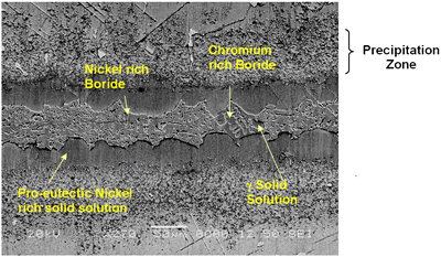
| | Figure 1. SEM secondary electron micrograph of centerline eutectic constituent. | | 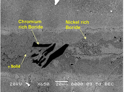
| | Figure 2. SEM backscatter electron micrograph of centerline eutectic constituent. | Table 3. Analysis of Metallic Constituents of Phases Observed in Brazed Joints. | | | Al | 1.34 | 0.04 | 0.81 | 3.27 | - | - | | Ti | 0.38 | 0.08 | 1.63 | 12.55 | 0.41 | 47.87 | | Cr | 18.54 | 93.98 | 11.40 | 3.48 | 2.29 | 1.29 | | Co | 2.39 | 0.41 | 2.68 | 9.22 | 1.77 | 0.14 | | Ni | 76.50 | 1.88 | 82.90 | 65.64 | 6.22 | 2.95 | | Nb | - | - | - | 2.46 | 14.56 | 21.04 | | Mo | 0.3 | 2.32 | 0.27 | 0.39 | 1.23 | 2.62 | | W | 0.54 | 1.29 | 0.29 | 2.61 | 2.58 | 4.03 | | Ta | - | - | - | 0.39 | 28.02 | 20.06 | Ohsasa et al. [4] in their experiment on numerical modeling of transient liquid phase bonding of nickel using Ni – B – Cr ternary filler metal calculated, using Scheil simulation, the solidification behavior of the residual liquid during cooling stage. They reported that a ternary invariant centerline eutectic consisting of Ni base FCC solid solution phase, a Ni boride (Ni3B) and a Cr boride (CrB) formed at 1097oC. Their simulation showed that during the solidification of residual liquid in a sample held at 1100oC, a Ni rich FCC phase formed as the primary phase. This was followed by a eutectic reaction L → FCC γ + Ni3B at 1042oC. Solidification was reported to be completed by a ternary eutectic reaction L → FCC γ + Ni3B + CrB at 997oC. Similarly, in the present work, involving a Ni-Cr-B filler alloy, the formation of terminal ternary eutectic along the center region of the joint is in agreement with Gibb’s phase rule which requires the invariant eutectic reaction to consist of four different phases (i.e. liquid and the three phases of the solid eutectic). The average hardness of the eutectic, measured by microhardness tester, was found to be 720 VHv, which is much higher than the hardness of the base metal (410 VHv). The influence of brazing temperature and holding time on the formation of this centerline eutectic was studied by plotting the average width of the eutectic microstructure, measured by SEM examinations, against the square root of holding time. The plot is shown in Figure 3. | 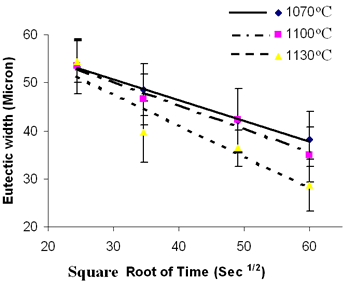
| | Figure 3. Eutectic width against Root of Holding Time. | It is seen that the eutectic width decreased linearly with an increase in square root of holding time at each brazing temperature. Also demonstrated by the plot is a decrease in the eutectic width at each holding time with increase in brazing temperature. These indicate a diffusion controlled migration of the solid-liquid interface during isothermal holding at the respective brazing temperatures with the distance of penetration of the diffusing specie being proportional to the square root of time [5]. Boron is known to depress the melting point of nickel, and an insufficient diffusion of this element from the braze region into the base material will result in persistence of liquid phase along the joint region. These observations, thus, strongly suggest that the centerline eutectic actually formed from the residual liquid that was present at the end of each holding time, which subsequently transformed into constituents with eutectic-type morphology. In order to confirm this suggestion, 30 μm and 60 μm gap samples were held for 60 min at 1100oC. Microstructural examination of these samples showed that isothermal solidification was completed in the 30 μm sample (Figure 4), with its microstructure consisting of mainly solid solution phase, in contrast to the 60 μm sample (Figure 5) where centerline eutectic formed as a result of insufficient time for isothermal solidification. | 
| | Figure 4. Microstructure of 30 μm gap brazed at 1100oC for 1 h. | | 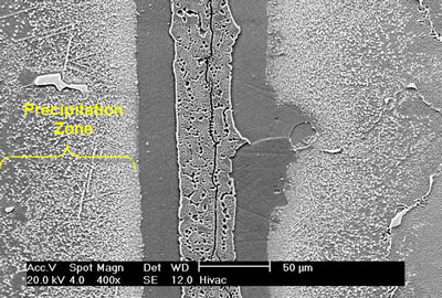
| | Figure 5. Microstructure of 60 μm gap brazed at 1100oC for 1 h. | Bands of irregular shaped nickel rich borides were observed on the braze side of the substrate-braze interface in samples brazed at 1070oC (Figure 6). | 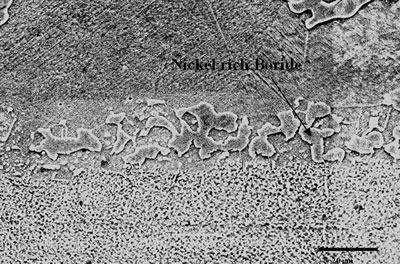
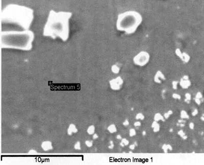
| | Figure 6. Secondary electron image of “NB 150” brazement showing Ni rich interface boride. | Gale et al. [6] in their work on diffusion brazing of Ni using an insert of Ni-B-Si alloy, reported a significant precipitation of Ni3B in the vicinity of the original position of substrate – insert interface. In addition, extensively distributed fine globular precipitates within the base metal grains and along the grain boundaries adjacent to substrate – braze interface, were observed in all the samples brazed at different temperatures and holding time. The number density of these particles declined in a gradual fashion with increasing distance from the bond line (Figures 1, 5 and 7). SEM energy dispersive X-ray microanalysis showed that, the particles were chromium based and were relatively rich in boron compared to the adjacent gamma matrix (Figures 8a, b). Boride precipitation, however, is in contrast to the conventional TLP bonding models, which assume rapid equilibration of the solid and liquid phases to their respective solidus and liquidus compositions upon a complete melting of the interlayer. This is then followed by solid state diffusion of the melting point depressant in the base alloy, resulting in a gradual isothermal solidification of the insert without the precipitation of second phases. | 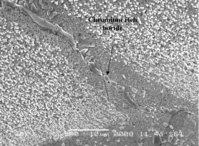
| | Figure 7. Chromium rich boride along the grain boundary adjacent to braze-substrate interface. | | 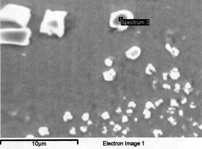
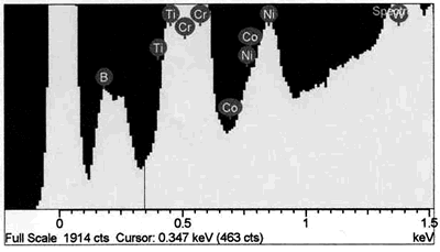
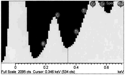
| | Figure 8. EDS analysis comparison of boride phase (a) and braze austenitic solid solution phase (b) confirming partitioning of boron into second phase during bonding. | Conversely, it appears from the experimental results that the chromium boride precipitates formed as a result of diffusion of boron exceeding the solubility limit at the bonding temperature (before solid-liquid equilibration) during the initial stages of joint formation. It is generally believed that, for optimum properties boron should be present at a level which fully saturates the grain boundaries in a superalloy but does not allow the formation of boride particles. Jena and Chaturvedi [7] had suggested that grain boundary borides in superalloys could be harmful to its properties. Considering the high chromium content and extensiveness of the precipitation, this could lead to a significant depletion of chromium around this region of the substrate, resulting in a dramatic decrease in the corrosion resistance. Such a situation in which corrosion resistance depended essentially on the chromium content in intergranular regions controlled by Cr5B3 and CrB precipitation has been previously reported [8]. Likewise, formation of eutectic constituent along the center region of the joint and the bands of nickel base boride could be deleterious to the properties of brazed materials. The low melting temperature of these boron rich eutectic constituents could lower the service temperature of brazed components. Moreover, presence of continuously distributed hard eutectic constituent along brazed joint is potentially harmful to mechanical properties. This was actually confirmed in samples where the centerline eutectic microstructure served as a preferred low resistance path to crack propagation (Figures 2 and 5). It should also be mentioned that, even though complete isothermal solidification was achieved in 30 μm gap samples brazed for 60 min at 1100oC, with preclusion of centerline eutectic, post braze heat treatment might yet be required for optimum joint microstructure and performance. Post braze heat treatment will further homogenize the joint both chemically and microstructurally with the base metal. Microstructure of “DF3” Brazement A backscatter electron SEM microstructure of a sample brazed with “DF3” at 1195oC for 20 min and then annealed at 1065oC for 4 h is shown in Figure 9. The microstructure is seen to consist of three different dispersed intermetallic phases in a nickel solid solution matrix. The EDS-SEM chemical composition analysis was carried out, and representative EDS spectra of MC carbide and base metal are shown in Figure 10a and b, respectively. They show the three precipitates to be MC carbides, chromium based boride/carbon-boride phase and elongated Ni3Ti based intermetallic phase, Table 3. The MC carbide particles that formed in the joint area were found to have composition similar to those present along the base alloy grain boundaries (Tables 3 and 4). The average microhardness of the central area of the brazement was found to be 830 VHv, which is more than 200% of that of the base alloy. The high hardness value can be attributed to the presence of hard intermetallic particles. These particles are formed by solidification of the residual liquid on cooling from the brazing temperature. The dispersed nature of the second phase particles in the “DF3” brazement, as compared to the presence of continuously distributed centerline eutectic in “NB 150”, can be attributed to the initial compositional difference between the fillers, which was also reflected in the higher hardness of “DF3” brazement. In addition, the presence of La is known to assist in suppressing the formation of borides with chain like morphology, and contributes to microstructural spheroidization. Table 4. Analysis of Metallic Constituents in MC Carbide in the Base Alloy. | | | Atomic % | 47.87 | 1.29 | 0.14 | 2.95 | 21.04 | 2.62 | 20.06 | 4.03 | Conclusions • The microstructure of brazements of IN 738 superalloy, brazed with “NB 150” filler alloy at different brazing temperatures (1070 - 1130oC) and for varying holding times (10 – 240 min) was studied. It consisted of eutectic-type constituents formed in the center of the brazements from the residual liquid, which was present after the holding times at the brazing temperature. • The average width of the eutectic microstructure decreased with holding time at each bonding temperature, and the isothermal solidification rate was observed to increase with an increase in brazing temperature. • In “DF3” brazements, MC carbide, Ni3Ti based intermetallic and chromium rich boride / carbon- boride phases were observed along the center-area of the joint. Acknowledgments The authors would like to gratefully acknowledge the financial support from NSERC of Canada and a consortium of Manitoba aerospace industries. They are also grateful to Standard Aero Ltd. Winnipeg for the use of their facilities for vacuum brazing and supplying the filler alloys. O. A. Ojo gratefully acknowledges the award of a graduate fellowship by the University of Manitoba. References 1. I. Buschke and E. Lugscheider, “New approaches for joining high-temperature materials”, Materials Solutions 98, Joining of Advanced and Specialty Materials, ASM International, Rosemont, IL, (1998) 51-55. 2. E. Lugscheider, H. Schmoor and U. Eritt, “Optimization of repair-brazing processes for gas turbine blades”, Brazing, High Temperature Brazing and Diffusion Welding, Deutscher Verlag fur Schweisstechnik GmbH, Dusseldorf (Germany), (1995) pp. 259-261. 3. D. S. Duvall, W. A Owczarski and D. F. Paulonis, “TLP Bonding--a New Method for Joining Heat Resistant Alloys”, Welding J., April (1974) 203-215. 4. K. Ohsasa, T. Shinmura and T. Narita, “Numerical Modeling of Transient Liquid Phase Bonding Process of Ni Using Ni-B-Cr Ternary Filler Metal”, Journal of Phase Equilibria, 20 (1999) 199-206. 5. J. Crank, “The Mathematics of Diffusion”, Clarendon Press Oxford, London, 2nd ed., (1975) p. 37. 6. W. F. Gale and E. R. Wallach, “Microstructural Development in Transient Liquid-Phase Bonding”, Metall. Trans. A, 22A, Oct. (1991) 2451-2457. 7. A. K. Jena and M. C. Charturvedi, “The Role of Alloying Elements in the Design of Nickel-Base Superalloys”, (Review) Journal of Mat. Sci., 19 (1984) 3121-3139. 8. B. Jahnke and J. Demny, “Microstructural Investigations of A Nickel-Based Repair Coating Processed by Liquid Phase Diffusion Sintering” Paper presented at the Inter. Conf. on Metallur. Coatings, San Diego, U.S.A., April 18-22, 1983, Elsevier Science SA, Lausanne (Switzerland), (1983) pp. 225-235. Contact Details |