Introduction The main disadvantage of monolithic ceramics for structural components is their brittleness and low reliability. Even for the monolithic ceramics with high toughness, macroscopic inelasticity has not been achieved [1]. Design with such materials must be based on elastic stresses, combined with weakest link scaling and extreme value statistics. Continuous fiber reinforced ceramic matrix composites (CMCs) are specifically tailored so that crack-wake processes result in high fracture resistant materials [2-4]. The distributed matrix cracking and resultant fiber bridging redistribute stresses around strain concentration sites and increase toughness and reliability. It is noted that the inelastic strain eliminates stress concentrations and scaling effects, enabling design procedures similar to those used for metals [1,2]. To obtain high fracture toughness and thermal shock resistance, CMCs were designed with a weak interface between fibers and matrix, e.g., the interface in SiC fiber reinforced SiC matrix composites (SiC/SiC) coated by carbon. The weak interface can cause a crack to deflect along the interfaces, permitting intact fibers to bridge crack faces. However, although the use of weak interfaces can increase fracture toughness and thermal shock resistance, it may not be compatible with creep and fatigue resistance at high temperatures, which demands strong interfaces resisting the nucleation and growth of cavities. Therefore, it is necessary to study cyclic fatigue and creep of CMCs for their applications. It has been found that the fatigue limit can be as high as 80% of the ultimate tensile stress (UTS) at room temperature [5,6]. One of the mechanism responsible for the enhanced microstructural damage during fatigue in SiC/SiC appears to be related to the wear along the sliding fiber-matrix interface, which may lead to fiber damage (e.g., carbon fiber) and lower its failure stress [5,6]. Although fatigue strength of CMCs at room temperature is high, it decreases with an increase in testing temperature even if the temperature is lower than that for fiber creep occurring. In this paper, some new experimental results are presented to show mechanical characteristics of damage tolerant CMCs. Moreover, several suggestions for improving performance of CMCs and expanding applications are given based on the research results. Experimental The composites used in the present investigation were SiC/SiC processed by chemical vapor infiltration (CVI) and Al2O3/Al2O3 processed by slurry paste and sintering [7-15]. The tensile specimens were machined from the panels using diamond cutting tools. The smooth specimens for the monotonic tension, creep and cyclic fatigue tests were 10 mm in width and 3 mm in thickness [7,8]. The double notched specimens were used to study notch sensitivity [15]. All the mechanical tests were carried out with a servo-hydraulic testing system in argon or air. The fatigue tests were performed with sinusoidal loading frequency of 20 Hz. The stress ratio (R), which was defined as the ratio of minimum stress to maximum stress, was 0.1 for fatigue tests. Creep tests were conducted under a constant load. Creep strain was measured directly from the gage length of the specimen by a contact extensometer (MTS Model 632.53-F71, MTS System Corporation, Minnesota, USA), which has measuring range of ±2.5 mm over its gage length of 25 mm. Repeated unloading-reloading with a rate of 50 MPa/s was applied to measure the modulus change during the creep tests. The specimens were allowed to soak over 30 min at high temperatures before starting creep or cyclic fatigue tests. The fractured specimens were examined by both optical microscopy and scanning electron microscopy (SEM). Results and Discussion Monotonic Tension The tensile stress-strain in SiC/SiC composite shows that inelastic deformation occurs at a stress of 70 MPa after linear elastic deformation, as shown in Figure 1. The tensile strength and ductility of the SiC/SiC at high temperatures are higher than at room temperature [5]. This is considered the weak interface is beneficial for strength and ductility by avoiding fiber fracture. | 
| | Figure 1. Tensile stress-strain curves in SiC/SiC composite at room and high temperature in argon. | The notch sensitivity of the composites is examined using tensile maximum gross stress of the composite, σgcu. Here, the maximum gross stress is defined as:  (1) (1)
where F*cu is the maximum tensile load, 2W is the specimen width, and t is the specimen thickness. The plots of σgcu versus a/W (a is notch length) are shown in Figure 2. Because of the gage length dependence of the tensile maximum stress of the composite, the obtained strength by the specimen with a gage length of 40 mm and a width of 20 mm is used as the tensile strength, σcu. This gage length is the same as that of the double edge notched (DEN) specimen. If the composite exhibits complete notch insensitivity, the plots of σgcu versus a/W should follow the relationship,  (2) (2)
| 
| | Figure 2. Notch Length to Width Ratio, a/W. | Although the values are scattered, the relations for both the loading directions follow the straight line predicted by Equation (2), suggesting the notch insensitive nature of the composites. Observation of the fracture appearance of the DEN specimen loaded in θ=00 direction shows that the fracture path terminates between notch tips although the path is not straight (example indicated by arrows). In addition, a large damage zone from the notch tip spreads in the ligament area of the specimen. A large nonlinearity in the tensile stress-strain curve is probably due to spreading of this large damage zone [15]. The composite for θ=450 off axis loading also shows complete notch insensitivity. The fracture path is independent of the existence of the notches and the path is obviously slanted against the loading axis (example indicated by arrows). The notch insensitive behavior of the composite under this loading is quite reasonable because the failure of the specimen occurs independent of the existence of notches, i.e., the crack path is independent of the notches. In the through-the-thickness direction, shear failure between woven fabric sheets is clearly visible in the tested specimen and this failure behavior is very similar to that observed in the un-notched specimen. Fatigue and Creep The cyclic fatigue life at room and high temperatures is shown in Figure 3. The stress-life curve at 1000°C can be divided into three regimes. One is the low cycle regime (<104 cycles), in which the stress exponent for fatigue life is high and there is no significant difference in fatigue life between room temperature and high temperatures, although the slope of the curve at the latter seems higher. The second regime is the rapid decrease in fatigue life with stress at 1000°C when the stress is lower than 180 MPa. There is no second regime at room temperature. This means that the second regime depends on temperature. This will be discussed later. The third regime exhibits a fatigue limit defined by the specimens below it having a life over 107 cycles. The fatigue limit at 1000°C is only 75 MPa, which is about 30 % of UTS. The fatigue limit at room temperature is 160 MPa (about 80 % of UTS). | 
| | Figure 3. The maximum stress versus cycles to failure for cyclic fatigue in SiC/SiC composite at room and high temperature in argon. | Although UTS and the proportional limit at 1000°C are higher than those at room temperature, the fatigue limit at 1000°C is much lower than that at room temperature. This means that the fatigue limit is not proportional to the monotonic tensile strength. This point is important for composite design, since monotonic strength is not useful for designing CMCs for high temperature applications. The fatigue limit of the composite at room temperature is much higher than the stress of the matrix cracking. This means that the composites can avoid the unsteady propagation of the matrix cracks induced by the first loading during cyclic fatigue at the stress of the fatigue limit. In other words, the matrix cracks formed on the first loading may propagate and also the microcracking of the matrix may continue over several thousand cycles, but they are finally arrested and remain stationary during later cyclic loading. The fiber bridging is commonly thought to be the main reason for this phenomenon, since the bridging force decreases the stress intensity at crack tip. At stresses above the fatigue limit, cyclic fatigue fracture occurs accompanied by the modulus reduction with cycles. The reduction of modulus can be caused by the increase of either crack number or crack length. Therefore, any factor (cyclic loading, high temperature creep, oxidation, etc.) can lead to decrease of the modulus (life) of a specimen if it can increase crack number or crack length. The available theory and experiments on CMCs are mostly applicable to unidirectional fiber reinforced composites. For 2D woven SiC/SiC composite, the basic elements are 0° bundles, 90° bundles and pores. Therefore, their interaction must be taken into consideration to explain mechanical properties. The matrix microcracking occurs during initial application of a creep load, therefore fiber bridging of matrix cracks always operates whether creep rate of fibers is higher or lower than the matrix. In the crack bridging mechanism, matrix crack growth rate is governed by a process in which the increase in the crack length is accompanied by an increase in the number of fibers bridging the crack. This continues up to a steady state condition produced by the competition between creating more bridged fibers as the crack length increases and the fracture or creep of these fibers as more stress is transferred to them by the increased crack-opening displacement. Therefore, the effects of creep resistance of the bridged fibers on creep behavior of the composite are important. Modulus Change and Microscopic Damage The gradual modulus degradation in cyclic fatigue has been reported for the unidirectional and laminated ceramic composites at room temperature and elevated temperatures. It has been shown that the gradual damage growth accompanies modulus decrease in the CMCs under fatigue loading. To understand the damage evolution and degradation mechanism during fatigue and creep, Young's moduli were measured. Figure 4 shows the evolution of the stress strain hysteresis loops. The slope decreases and the width of the loops increases with cycles. | 
| | Figure 4. Evolution of the hysteresis loops during fatigue in SiC/SiC composite at 1300°C under the maximum stress of 120 MPa in air. | The former indicates the decrease of the modulus and the latter means the decrease of the interfacial sliding resistance. The hysteresis loops shift to the right along the strain axis, which is known as ratchetting due to time-dependent deformation (e.g., creep). The modulus normalized by the value from the linear part during the first loading versus cycles is shown in Figure 5. At the stresses ≥ 120 MPa, the modulus decreases rapidly within 10 cycles, and then goes to gradual decrease stage, and finally drops fast up to fracture. At the stresses ≤ 105 MPa, the modulus is constant up to 104 cycles and then monotonously decreases. At 75 MPa, the modulus is constant up to 107 cycles, at which the test was stopped. When the modulus decreases to 20-40% of the original value, the specimens are fractured. | 
| | Figure 5. Young’s modulus change during fatigue in SiC/SiC composite at 1300°C under different stresses in air. | Creep and fatigue cracks are always found at the large pores between fiber bundles (Figure 6). When cracks meet 0° fibers, debonding of interfaces between fibers and the matrix occurs. The 0° fibers bridge crack faces and therefore decrease the driving force at the crack tip as a general bridging mechanism. | 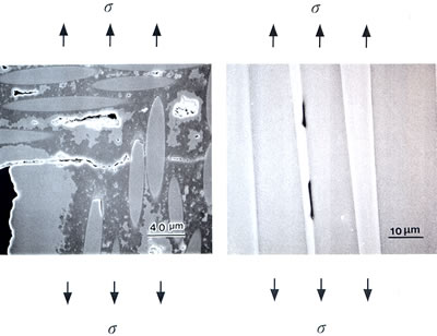
| | Figure 6. Cracks in SiC/SiC composite at 1300°C. | Conclusions Monotonic tension, fatigue and creep of CMCs have been studied. The inelastic deformation causes stress redistribution at notch tip, as a result, notch insensitivity and little scaling effect appear in CMCs. However, the high monotonic strength does not mean the time-dependent properties (fatigue or creep) at high temperatures are also promising. Creep and interfacial friction control cyclic fatigue life at high temperatures. Acknowledgements We are very grateful for the advice and assistance of Dr. M. Mizuno and Mr. S. Ogawa in Japan Fine Ceramics Center, Nagoya, Japan. References 1. A. G. Evans, “Perspective on the Development of High-Toughness Ceramics”, J. Am. Ceram. Soc., 73 (1990) 187-206. 2. A. G. Evans and F. W. Zok, “The Physics and Mechanics of Brittle Matrix Composites”, J. Mater. Sci., 29 (1994) 3857-3896. 3. A. G. Evans, F. W. Zok and R. M. McMeeking, “Fatigue of Ceramic Matrix Composites”, Acta Metall. Mater., 43 (1995) 859-875. 4. A. G. Evans, "Design and Life Prediction Issues for High-Temperature Engineering Ceramics and Their Composites", Acta Mater., 45 (1997) 23-40. 5. M. Mizuno, S. Zhu, Y. Nagano, Y. Sakaida, Y. Kagawa and M. Watanabe, “Cyclic Fatigue Behavior of SiC/SiC Composite at Room and High Temperatures”, J. Am. Ceram. Soc., 79 (1996) 3065-3077. 6. S. Zhu, M. Mizuno, Y. Kagawa, J. Cao, Y. Nagano and H. Kaya, “Creep and Fatigue Behavior of SiC-fiber/SiC Composite at High Temperatures”, Mater. Sci. Eng., A225 (1997) 69-77. 7. S. Zhu, M. Mizuno, Y. Nagano, J. Cao, Y. Kagawa and H. Kaya, “Creep and Fatigue Behavior of Enhanced SiC/SiC Composite at High Temperatures”, J. Am. Ceram. Soc., 81 (1998) 2269-2277. 8. S. Zhu, M. Mizuno, Y. Kagawa, J. Cao, Y. Nagano, and H. Kaya, “Creep and Fatigue Behavior in Hi-NicalonTM-Fiber-Reinforced Silicon Carbide Composites at High Temperatures,” J. Am. Ceram. Soc., 82 (1999) 117-128. 9. S. Zhu, M. Mizuno, Y. Kagawa and Y. Mutoh, “Monotonic Tension, Fatigue and Creep Behavior of SiC-Fiber Reinforced SiC Matrix Composites: A Review”, Comp. Sci. Tech., 59 (1999) 833-851. 10. S.J. Zhu, “Fatigue and Creep Characteristics of Fiber Reinforced Ceramics (Overview)”, Materia Japan, 38 (1999) 420-424. In Japanese. 11. Y. Kaneko, S. Zhu, Y. Ochi, T. Ogasawara, T. Ishikawa, “Effect of Frequency on Fatigue Behavior in Tyranno Fiber-reinforced SiC Composites”, Ceram. Eng. Sci. Proc., 22 (2001) 553-560. 12. T. Mamiya, S. Zhu, Y. Kagawa, “Application of Dielectric Properties to Noncontact Damage Detection for Continuous Fiber-Ceramic Matrix Composites”, Ceram. Eng. Sci. Proc., 22 (2001) 717-724. 13. T. Ogasawara, T. Ishikawa, Y. Ohsawa, Y. Ochi, and S. Zhu, Tensile Creep Behavior and Thermal Stability of Orthogonal 3-D Woven Tyranno ZMI Fiber /Si-Ti-C-O Matrix Composites , J. Am. Ceram. Soc., 85 (2002) 393-400. 14. Y. Miyashita, K. Kanda, S. Zhu, Y. Mutoh, M. Mizuno and A. J. McEvily, “Observations of Fatigue Damage Process in SiC/SiC Composites at Room and Elevated Temperatures”, Inter. J. Fatigue, 24 (2002) 241-248. 15. T. Mamiya, H. Kakisawa, W.H. Liu, S.J. Zhu and Y. Kagawa, “Tensile Damage Evolution and Notch Sensitivity of Al2O3 Fiber-ZrO2 Matrix Minicomposite-reinforced Al2O3 Matrix Composites”, Mater. Sci. Eng., A325 (2002) 406-414. Contact Details |