|
For the economical manufacture of tensile specimens from sheet steel. Due to the low cutting speed and the shape of the blanking tool, the work-hardening of the cut edge amounts to max. 10 % of the specimen thickness. The slight punch oversize – and thus the work-hardening – is removed with the specimen grinder.
Cutting force P in kN

If P ≥ 650 kN, then
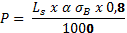
Table 1. Specimen Blanking Presses for Cutting Force from 200 to 1.500 kN
|
|
|
Structural shape
|
C-frame
|
O-frame
|
O-frame
|
O-frame
|
|
Cutting force - kN
|
500
|
650
|
1000
|
1500
|
|
Specim. throughput - 1/min
|
6
|
6
|
6
|
6
|
|
Specim. thickness - mm
|
0.2 - 6
|
0.2 - 6
|
0.2 - 6
|
0.2 - 8
|
|
Max. power cons. - kVA
|
4
|
4
|
4
|
10
|
Table 2. Typical Flat Specimens for the Tensile Test
|
|
|
|
a
|
b
|
L0
|
B
|
Lc
|
L
|
∆b
|
|
DIN EN 10002, type 1
|
|
12,5
|
50
|
|
75
|
165
|
0,003
|
|
DIN EN 10002, type 2
|
|
20
|
80
|
30
|
120
|
≥250
|
0.052
|
|
DIN 50 114
|
≤3
|
20
|
80
|
30
|
120
|
≥250
|
|
|
DIN 50 125
|
3
|
8
|
30
|
12
|
38
|
≥115
|
|
|
|
5
|
16
|
50
|
22
|
65
|
≥175
|
|
|
|
6
|
20
|
60
|
27
|
80
|
≥210
|
|
|
|
8
|
25
|
80
|
33
|
105
|
≥260
|
|
|
JIS Z 2201 (13A)
|
|
20
|
80
|
30
|
120
|
|
|
|
JIS Z 2201 (13B)
|
|
12.5
|
50
|
20
|
60
|
|
|
|
JIS Z 2201/ 5)
|
|
25
|
50
|
30
|
60
|
|
|
|
JIS Z 2201/1B)
|
|
25
|
200
|
30
|
220
|
|
|
|
JIS Z 2201/1A)
|
|
40
|
200
|
220
|
|
|
|
|
ASTM E8
|
|
12.5
|
50
|
20
|
60
|
≥200
|
0.05
|
|
|
|
40
|
200
|
50
|
225
|
≥450
|
0.1
|
Table 3. Typical Round Specimens (Figure “specimen types”, b)
|
|
|
|
d
|
L0
|
D
|
Lc
|
L
|
|
DIN EN 10002 (Annex C)
|
≤4
|
100/200
|
|
L0 + 50
|
|
|
DIN 50125, shape A
|
10
|
50
|
12
|
≥60
|
≥140
|
|
|
12
|
60
|
15
|
≥72
|
≥160
|
|
|
16
|
80
|
20
|
≥96
|
≥205
|
|
ASTM E8
|
12.5
|
50
|
|
60
|
|
|
|
8.75
|
35
|
|
45
|
|
|
JIS Z 2201 No 4
|
14
|
50
|
|
60
|
|
Specimen Grinding Machine Zwick 7120
Specimen Grinding Machine Zwick 7120 is used for grinding specimens to shape and size. Exact grinding dimensions of the parallel specimen length through vertical adjustment of the entire grinding unit (max. power consumption 0.75 kVA)
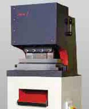
Figure 1. Specimen blanking press
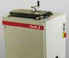
Figure 2. Specimen grinding machine
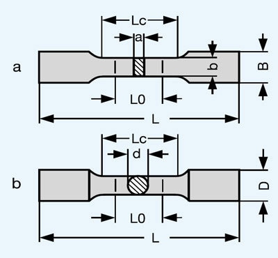
Figure 3. Specimen types
Materials Testing Machines
Field of Application
Materials testing machines are predominantly used for the determination of the strength and deformation behaviour of specimens and components. For this purpose, tensile, compression, flexure or shear tests and with special devices even torsion tests are carried out. These testing machines have large test areas, test travels, speed ranges, exchangeable test tools and test data transducers etc. to enable tests to be carried out both on specimens and components of different shapes and dimensions made of most different materials and material combinations and of different properties.
Basic Concept
The Zwick program includes testing machines in table-top and floor standing design with different measurement and control systems, load frames, drives and versatile function and supplementary units. However in order to be able to offer the best machine for each requirement, Zwick has developed a user-related concept. The user can choose among three machine lines, each of them being completely different as to equipment, performance features and also as to the capability of expansion:
- BasicLine
- Standard Line
- Allround Line
The decisive testing machine component is the measurement and control system. Its conception and its scope of performance decide which drive can be controlled, which measurement system can be connected to it and which functions can be controlled with it – and they thus determine the range of application and the testing machine’s capability for future expansion.
The advantages to the user of the three different testing machine versions are as follows:
- The BasicLine is particularly suitable for function tests on component parts and for the simple materials test.
- The Standard Line is ideal to solve simple test jobs reliably. It is a low-cost, sturdy solution which covers many testing needs.
- The Allround Line is the basis for a large spectrum of demanding test jobs and can easily be expanded with the requirements becoming more demanding. It is thus a solution that can be relied on for future requirements.
Measurement and Control System BasicLine
The electronics taken from existing Zwick machine types guarantees a very high availability and reliability of the test system. The measurement and control electronics is compactly packed in a housing. BasicLine testing machines can be operated in the Stand Alone mode without PC and can be operated directly via function keys on the testing machine. As standard it is additionally possible to operate the BasicLine with the test software testXpert®, thus profiting from all advantages of standardized test programs and from the many years of experience on the development sector.
Measurement and Control System testControl (For The Standard and Allround Version)
By using most state-of-the-art technologies and by granting highest quality standards, testControl offers a maximum of technical performance and a long-term investment guarantee. These are the particular features of testControl:
- Time-synchronous test data acquisition with high resolution and measuring frequency
- Real-time processing of the test data in a 500 Hz cycle for the monitoring and event-related test sequence control (e.g. speed change when reaching the yield or proof stress) and for safety limit values
- Adaptive control for exactly reproducible speeds and positions
- The measurement and control electronics and the power electronics for the drive system in question are compactly integrated in a housing. Thus, the usual cabling can be dispensed with.
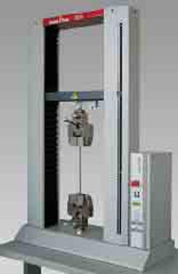
Figure 4. Materials testing machine BasicLine Z020
The measurement and control system testControl is available in 2 variants:
Stand Alone Variant
Easy and reliable operation via coloured display, 10-key keyboard and a few function keys – without PC. A printer may be connected directly for the printout of test results.
PC-Variant
The system may be configured and expanded to cope with the most different applications. PC and user software testXpert® make applications very comfortable and extremely flexible.
Load Frames
Different load frame versions for test loads up to 2.000 kN are available as standard. For special applications, special versions can be developed and manufactured, e.g. load frames in horizontal position suitable for the testing of long steel ropes.

Figure 5. Materials testing machine Z2.5 (zwicki) with testControl Stand Alone variant
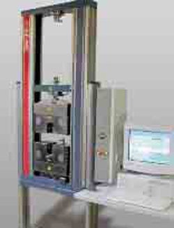
Figure 6. Materials testing machine Z050 with legs and testControl PC variant
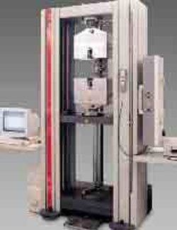
Figure 7. Materials testing machine Z100 with testControl PC variant
Single-Column Load Frame For Table-Top Testing Machines (Zwicki)
These load frames are designed with very rigid aluminum high precision extruded profiles. The working area is freely accessible from 3 sides. Thus, it is ideal for various tests on small parts and for Zwick hardness testing machines. It only requires a small floor space. Due to its light weight, it is easy to transport.
Two-Column Load Frames For Table-Top Testing Machines
The load frames of the BasicLine are designed with 2 round steel columns. The load frames of the Standard and Allround Line are designed with patented aluminium high-precision extruded profiles. They are light, very rigid and serve simultaneously as lead-screw guide and protection. T-shaped grooves on the outer sides allow a simple fitting of accessories as e.g. safety devices without being impeded by the crosshead. All load frames with two profiles – except for the BasicLine – can be equipped with legs.
Advantages are:
- Positioning of the working area to an optimum height for the user
- Comfortable seated operation with absolute freedom for leg movement (making it also suitable for wheelchair users)
Load Frame For Floor Standing Models
The two supporting and guide columns of load frames for test loads up to 150 kN are also patented aluminium high-precision extruded profiles. When using load frames for higher test loads, 2 or 4 hard-chrome plated round steel columns are used. For testing machines with a hybrid drive system the stationary piston rods are at the same time used as supporting and guide columns. All load frames with an electro-mechanical drive system may optionally be equipped with a second working area allowing e.g. a rapid change of the test mode without having to change the equipment.
Table 4. Features of the BasicLine, Standard and Allround Line
|
|
|
Load frame
|
|
|
|
|
Type of set-up
|
|
|
|
|
Table-top machine (nominal load)
|
500 N to 20 kN
|
1 kN to 150 kN
|
1 kN to 150 kN
|
|
Floor stand. machine (nominal load)
|
-
|
50 to 2.000 kN
|
50 kN to 2.000 kN
|
|
Support and guide columns
|
|
|
|
|
No. of columns
|
2
|
2 or 4
|
2 or 4
|
|
No. of aluminium profiles
|
1 (Z0.5)
|
1 or 2
|
1 or 2
|
|
No. of working areas
|
1
|
1 or 2
|
1 or 2
|
|
Expanded design (higher and/or larger)
|
-
|
yes
|
yes
|
|
|
|
Electro-mechanical
|
|
|
|
|
No. of ball screws
|
1 or 2
|
1 or 2
|
1 or 2
|
|
DC-Motor
|
yes
|
only zwicki
|
only zwicki
|
|
AC-Motor
|
-
|
up to 600 kN1
|
up to 600 kN1
|
|
Servohydraulic
|
-
|
from 400 kN2
|
from 400 kN
|
|
Hybrid
|
-
|
-
|
from 400 kN
|
|
|
|
BasicLine (also usable without PC)
|
yes
|
-
|
-
|
|
testControl PC-variant (Standard)
|
-
|
yes
|
yes
|
|
testControl Stand Alone variant (Option)
|
-
|
optional
|
optional
|
|
|
|
test software testXpert® (with PC)
|
optional
|
optional
|
optional
|
|
|
|
Strain gauge load cell
|
1 (interchangeable)
|
1 (optional up to 2)
|
1 (optional up to 3)
|
|
Digital crosshead travel monitor
|
integrated
|
integrated
|
integrated
|
|
Digital extensometer
|
-
|
optional 1
|
yes (optional up to 3)
|
|
Analog extensometer
|
-
|
optional 1
|
yes (optional up to 3)
|
|
|
|
Digital extensometer
|
-
|
yes
|
yes
|
|
Analog extensometer
|
-
|
yes
|
yes
|
|
Analog reduction-in-width monitor
|
-
|
yes
|
yes
|
|
Video Capturing
|
-
|
yes
|
yes
|
|
Switch Contact
|
-
|
yes
|
yes
|
|
Switch Control
|
-
|
yes
|
yes
|
|
Further measurement systems
|
-
|
yes
|
yes
|
|
|
|
Specimen grips (mot., pneum., hydr.)
|
-
|
-
|
yes
|
|
Extensometer systems
|
-
|
semi-automatic
|
fully automatic
|
|
|
|
Torsion drive
|
-
|
-
|
yes
|
|
Torque transducer
|
-
|
-
|
yes
|
|
Multi-channel force measuring system
|
-
|
-
|
Yes
|
|
High-temperature testing equipment
|
-
|
(yes)
|
Yes
|
|
Low-temperature testing equipment
|
-
|
(yes)
|
yes
|
Drives
Electro-Mechanical Drive Systems
The basis of all electro-mechanical drive systems are backlash-free and low-friction ball screws and digitally controlled drive systems. They are used with load frames for test loads up to 600 kN. Together with the digital measurement and control system they offer the following advantages:
- Extremely high, step-less speed range
- Very low speeds adjustable (from about 0.5 µm/min on)
- High-precision and exactly reproducible positions and speeds
The testing machines designed with single-column load frames (zwicki and BasicLine) are equipped with low-cost d.c. drives, all the others with particularly low inertia, brushless three-phase drives.
Hydraulic Drive Systems
This drive unit is located centrally on the upper fixed crosshead. Thus, the test area lying beneath is easily accessible. A servo- or proportional valve regulates the oil flow between hydraulic unit and differential cylinder. The oil cushion in the upper pressure area avoids the “piston jump” the rams are known for after the specimen break. The resolution of the piston travel transducer is 1.25 µm (less than 1/400.000 of the max. test travel). The hydraulic drive unit is the most economic solution particularly for high test loads.
Hybrid Drive Systems
In this patented drive unit, the advantages of the electromechanical drive (high precision) are combined with those of the hydraulic drive (high force density). The result is that even cylinders with high forces and long travels can be driven and positioned with an utmost accuracy. According to this principle 2 parallel synchronous cylinders coupled with the moving crosshead can regardless of the applied load be displaced exactly synchronously by following precisely and practically instantaneously the preselected position of an electronic pilot drive unit. The special features of this drive are the following:
- Large test stroke (no adjustment of the fixed crosshead required).
- Comparatively low height of the load frame.
Table 5. Load Frames and Drive Systems of the BasicLine
|
|
|
Type
|
table top
|
table top
|
table top
|
table top
|
|
Max. load, kN
|
0.5
|
5
|
10
|
20
|
|
Working area, max.
|
|
|
|
|
|
Height mm
|
596
|
561/1.061
|
1-041
|
1.041
|
|
Width mm
|
no limit
|
420
|
420
|
420
|
|
Depth mm
|
99.5
|
no limit
|
no limit
|
no limit
|
|
Max. crosshead speed mm/min
|
1.500
|
500
|
1.000
|
500
|
|
Crosshead travel resolution µm
|
0.226
|
0.05
|
0.09
|
0.045
|
|
Max. power consumption kVA
|
0.4
|
0.6
|
0.6
|
0.6
|
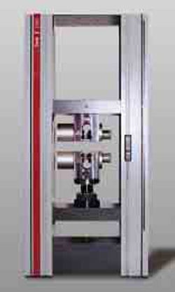
Figure 8. Materials testing machine Z400E
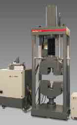
Figure 9. Materials testing machine Z1200H
Table 6. Load Frames and Drive Systems of the Standard and Allround Line (with Electro-Mechanical Drive System)
|
|
|
Type
|
table top
|
table top
|
table top
|
table top
|
table top
|
table top
|
table top
|
|
Max. test load, kN
|
1
|
2.5
|
5
|
10
|
20
|
30
|
50
|
|
Working area
|
|
|
|
|
|
|
|
|
Height, short, mm
|
-
|
573
|
-
|
-
|
-
|
-
|
-
|
|
Normal, mm
|
-
|
1073
|
1058
|
1058
|
1058
|
-
|
-
|
|
Higher, mm
|
1373
|
1373
|
1458
|
1458
|
1458
|
1380
|
1380
|
|
higher + larger, mm
|
-
|
-
|
-
|
1787
|
1787
|
-
|
-
|
|
Width, normal, mm
|
no limit
|
no limit
|
440
|
440
|
440
|
440
|
440
|
|
Larger, mm
|
-
|
-
|
-
|
640
|
640
|
-
|
-
|
|
Depth, mm
|
99.5
|
99.5
|
no limit
|
no limit
|
no limit
|
no limit
|
no limit
|
|
Crosshead speed
|
|
|
|
|
|
|
|
|
max., mm/min
|
1800
|
800
|
3000
|
2000
|
1000/20002
|
1000
|
600
|
|
Crossh. trav. Resolution, µm
|
0.0002
|
0.0001
|
0.041
|
0.027
|
0.014/0.054
|
0.027
|
0.016
|
|
Max. power consum., kVA
|
0.4
|
0.4
|
2/1.9
|
1.9
|
2.1/2.6
|
2.3
|
2.3
|
|
|
|
Type
|
floor stand.
|
table top
|
floor stand.
|
floor stand.
|
floor stand.
|
floor stand.
|
floor stand.
|
|
Max. test load, kN
|
50
|
100
|
100
|
150
|
250
|
400
|
600
|
|
Working area
|
|
|
|
|
|
|
|
|
Height, short, mm
|
-
|
-
|
-
|
-
|
-
|
-
|
-
|
|
Normal, mm
|
1824
|
-
|
1824
|
1715
|
1715
|
1800
|
1940
|
|
Higher, mm
|
-
|
-
|
-
|
-
|
-
|
-
|
-
|
|
Higher + larger, mm
|
1765
|
1360
|
1765
|
1660
|
1660
|
-
|
-
|
|
Width, normal, mm
|
630
|
640
|
630
|
630
|
630
|
630
|
740
|
|
Larger, mm
|
1030
|
-
|
1030
|
1030
|
1030
|
-
|
-
|
|
Depth - mm
|
no limit
|
no limit
|
no limit
|
no limit
|
no limit
|
no limit
|
no limit
|
|
Crosshead speed
|
|
|
|
|
|
|
|
|
max., mm/min
|
400/20001
|
200/15001
|
200/10001
|
900
|
600
|
250
|
200
|
|
Crossh. trav. Resolution, µm
|
0.027
|
0.026
|
0.0136
|
0.0123
|
0.0082
|
0.031
|
0.025
|
|
Max. power consum., kVA
|
5
|
6
|
5
|
5-5
|
6
|
7/132
|
20/262
|
| |
|
|
|
|
|
|
|
|
|
|
|
|
|
|
Table 7. Load Frames and Drive Systems for High Forces (Standard Types with Hydraulic or Hybrid Drive)
|
|
|
Max. test load, kN
|
400
|
600
|
1200
|
2000
|
600
|
1200
|
2000
|
|
Dimensions of load frame
|
|
|
|
|
|
|
|
|
Height, mm
|
2900
|
3000
|
3500
|
4200
|
2750
|
3147
|
4200
|
|
Width, mm
|
1020
|
1080
|
1300
|
1400
|
1530
|
1614
|
1870
|
|
Depth, mm
|
480
|
500
|
880
|
905
|
788
|
790
|
1100
|
|
Working area
|
|
|
|
|
|
|
|
|
max. height, mm
|
500
|
500
|
600
|
600
|
1895
|
2300
|
2400
|
|
with adjustable crosshead, mm
|
900
|
900
|
1000
|
1000
|
|
|
|
|
Width, mm
|
670
|
670
|
850
|
870
|
790
|
860
|
950
|
|
Max. travel, mm
|
500
|
500
|
600
|
600
|
850
|
1000
|
1-000
|
|
Travel resolution, µm
|
1.25
|
1.25
|
1.25
|
1.25
|
0.05
|
0.05
|
0.05
|
|
Max. test speed, mm/min
|
200
|
200
|
200
|
200
|
250
|
250
|
250
|
|
No. of columns
|
2
|
2
|
4
|
4
|
2
|
2
|
2
|
|
Max. power consum., kVA
|
8.5
|
8.5
|
15
|
23
|
8.5
|
15
|
23
|
|