Introduction Magnetorheological (MR) fluids belong to the general class of smart materials whose rheological properties can be modified by applying an electric field [1]. MR fluids are mainly dispersion of particles made of a soft magnetic material in carrier oil. The most important advantage of these fluids over conventional mechanical interfaces is their ability to achieve a wide range of viscosity (several orders of magnitude) in a fraction of millisecond [2]. This provides an efficient way to control vibrations, and applications dealing with actuation, damping, robotics and mechatronics [2-4]. However, by use of dynamic simulations software it is possible to analyze the behavior and performance of systems consisting of rigid or flexible parts undergoing large displacement motions [5]. Purpose Vibration control of vehicle suspensions systems has been an active subject of research, since it can provide a good performance for drivers and passengers [4]. Recently, many researchers have investigated the application of MR fluids in the controllable dampers for semi-active suspensions. This work has the purpose of characterizing, identifying the mathematical model and simulating the behavior of a MR fluid in car suspension systems. Methodology As discussed above, firstly, the characterization is made by means of experimentation and by using a prototype damper. The displacement of the damper is measured by stages meanwhile known compression forces are applied under the influence of different magnetic fields. Subsequently, the constitutive model is developed throughout the mathematical identification of the relationships of Force-Displacement, and Equivalent Damping Coefficient-Displacement. Polynomial expressions are derived as a function of electrical current to be an independent variable and displacement, force and velocity as dependent variables. Finally, the simulation is carried out in two parts. Part one; uses a program in which the constitutive model is used in order to adjust the damper resistance based on the necessary current and according to different modes of behavior that can simulate several kinds of road. And part two; the damper resistance is read by the module ADAMSVIEW of MSC ADAMS software in which a suspension system has been modeled for describing the damper displacements at different virtual road conditions. System Description The MR fluid used for this analysis, shown in Figure 1, it is mainly a dispersion of iron powder of 99.9% purity, as the soft magnetic material, in a carrier oil, and it was developed at ITESM, Campus Monterrey. The iron particle size distribution has a mean of 15.53 μm with standard deviation of 2.62 μm. The particles are irregularly shaped and the mass fraction of the solid phase is 60%. A commercial engine oil was used. The viscosity of the MR fluid varies from 800 cP to 150000 cP according to the magnetic field applied. Under the influence of a magnetic field the liquid phase separates form particles after more than 24 hours. | 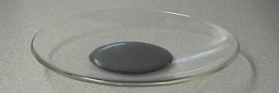
(a) 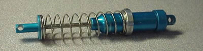
(b) | | Figure 1. (a) Magnetorheological fluid and (b) prototype damper. | The system used for the experiments is composed of the following components and presented in Figure 2. | 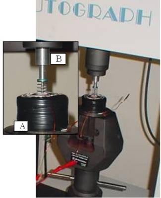
| | Figure 2. Experimental arrangement. (a) Coil and (b) Fastener. | The damper is a prototype made of aluminum with 0.112 m length, 0.014 m diameter and 3.6x10⁻⁶ m3 capacity. The common oil used inside the damper has been replaced with the magnetorheological fluid, which under no current, presents a similar behavior as the original fluid. A coil has been designed to be capable of producing a magnetic field of 70.8 kAm-1 at a current of 3 ADC, and it was designed to be located around the damper. Position A in Figure 2. A special fasten extremity was designed to fix the upper damper part to the universal test machine. Position B in Figure 2. The universal test machine used for this work was a SHIMADZU AG-1 250KN, which allows force measurements accuracy of ± 1% of indicated test force. The module ADAMSVIEW of MSC Software was used to create a virtual prototype of a suspension system and to view key physical measures that emulate the data normally produced physically. An equivalent damper coefficient (EDC) concept has been used. If the piston rod is translated at a velocity , this will require that the fluid trapped on one side of the piston squeeze through the spaces between the piston and the cylinder. The fluid action opposes the motion with a magnitude given by Eq. (1), where c is the equivalent damping coefficient. It is equivalent because the force exerted by the damper on the mass must not deviate from this expression no matter how fast or slow we move the mass [6]. , this will require that the fluid trapped on one side of the piston squeeze through the spaces between the piston and the cylinder. The fluid action opposes the motion with a magnitude given by Eq. (1), where c is the equivalent damping coefficient. It is equivalent because the force exerted by the damper on the mass must not deviate from this expression no matter how fast or slow we move the mass [6].  (1) (1)
Results Characterization of MR Damper The characterization of the magnetorheological damper has been carried out to obtain an expression, which represents its performance capabilities under different magnetic fields. Such expression establishes the way in which a controllable damping system can be fully used. Firstly, it is necessary to get the set of data for the determination of force-displacement and EDC-displacement relationship. The damper is fixed on the branches of the universal test machine; meanwhile a coil is located around the damper body, as shown in Figure 2. The tests were done both under triangular excitation at a constant velocity of 0.0007 m/s and at different electric current intensities through the coil, that vary from 0.5 to 3 Amperes. The velocity of 0.0007 m/s is selected because it represents low velocity, high equivalent damping coefficient in addition have a clear influence on the electrical current, as shown in Figure 3. A similar behavior has been found in reference [4]. The relationship obtained by experiments is shown in Figure 3. | 
| | Figure 3. EDC behavior at different velocities. | Constitutive Model Mathematical Identification The force-displacement relationship is obtained directly from the tests done, and the EDC-displacement relationship is obtained through the use of the EDC concept using the constant velocity of the tests and the force obtained from the following mathematical model. The constitutive model is obtained by mathematical identification of relationships force-displacements obtained from the test. Power equations, Eq. (2), have been found as a function of the displacement, δ, and electrical current, i. Figure 4 and Eq. (3), shown results for an applied current of 3 A.  (2) (2)
Where ƒ is the force required to overcome the resistance to compress the damper. And, δ is the displacement given by compression in the damper.  (3) (3)
| 
| | Figure 4. Mathematical identification of relationship force-displacement. | Once, all equations have been established, the constants a and b were plotted, as shown in Figure 5, to obtain general polynomial expressions, Eq. (4) and Eq. (5), in function of the current.  (4) (4)
 (5) (5)
| 
| | Figure 5. Analysis of (a) Constant a and (b) constant b. | Finally, a general power equation, Eq. (6), constituted by two polynomial expressions has been obtained:  (6) (6)
EDC is obtained and plotted, as Figure 6 shown, based on the constant velocity used in tests and the force obtained from equation (6) at 0.005 m, 0.01 m, 0.015 m, 0.02 m and 0.025 m displacements. | 
| | Figure 6. Equivalent Damping Coefficient analysis. | Similar to the previous analysis a general power equation, Eq. (7), has been obtained:  (7) (7)
The connection between the mathematical model and the software can be given by introducing the equivalent damping coefficient expression in function of the displacement. Simulation of MR Suspension System The use of computational software has played an important role in design. Computational techniques are being used to complement, reinforce and especially to reduce time and money spent on experiments and practical applications. Adjustment Of The Damper Resistance According To Constitutive Model A quarter suspension car has been designed in ADAMSVIEW software, as shown in Figure 7, based on a commercial car. The analysis of the suspension was done by simulating a collision between the car and an object at a velocity of 16.6 m/s. 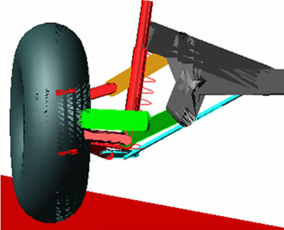
Figure 7. Quarter suspension car model. Once the design is completed, the damper coefficient value was modified by introducing a set of data points, which permits the software, based on an internal function, interpolate the discrete data. Such interpolation represents the EDC equation. Figure 8 shows the Modify Damper -Force window and the Input Data window. | 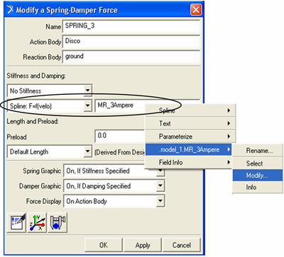
(a) 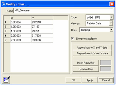
(b) | | Figure 8. (a) Damper modification window and (b) Data input window. | Damper Displacements At Different Virtual Road Conditions According with the results obtained from the comparative analysis, it is shown in Figures 9 and 10 a strong difference behavior between passive and semi-active suspension systems exist. The passive system shows a drastic change in the damper deformation and chassis displacement, meanwhile the semi-active system shows an adaptive behavior according to the respective damper displacement. | 
(a) 
(b) 
(c) | | Figure 9. Damper deformation comparison between semi-active systems, under low (a) and high (b) magnetic field, and passive suspension systems (c). | | 
(a) 
(b) 
(c) | | Figure 10. Chassis displacement comparison between semi-active systems, under low (a) and high (b) magnetic field, and passive suspension systems (c). | When the MR damper is under a low magnetic field the suspension system presents a smoother reaction compared with that of the passive suspension and a higher magnetic field. According with the results obtained from the analysis, it has been demonstrated that the equation obtained for the ECD made possible an appropriate response of the suspension system based on the magnetic field induced. Once the behavior of the MR suspension system has been demonstrated, a control algorithm is necessary to be developed and implemented, so that, the system responds according to the road conditions and the comfort required by the human being. Conclusions A magnetorheological fluid has been specially developed and incorporated into a damper prototype also specially used for this purpose. A set up with a designed load cell was used independent and also was mounted in an Autograph Shimadzu system in order to determine the force, velocity and displacements at different forces. The constitutive model is given by a mathematical power expression constituted by two polynomial expressions, which are in function of the electrical current. The suspension system is taken from a real model actually in use for a commercial automobile characterized by its design and excellent performance. The simulated system shown the movements and quantify the forces and displacements. The results obtained from a comparative analysis shows strong differences between passive and semi-active suspension systems. From the experiments and simulations carried out, it has been shown, the characterization of a damper can be made through the physical characteristics of the MR fluids, current, damper design and spring characteristics. In addition it has been shown that the use of ADAMS software is an excellent computational tool to simulate dynamic mechatronics systems. Finally a reconfigurable suspension system has been analyzed. Its ability to change its rheological properties in addition to its quick response to the circumstances makes the MR technology a feasible way to develop other reconfigurable systems. Future Work Future work involves the introduction of a couple systems in the simulator in order to reproduce real events for driving, to determine the details of mechatronics control and to improve the coil’s design for its implementation in a complete prototype. A control algorithm is necessary to be developed and implemented, so that, the system responds according to the road conditions and the comfort required by the human being. References 1. El Wahed Ali, K, et al., “Electrorheological an Magnetorheological fluids in blast resist design applications”, Materials & Design, 23 (2002) 391-404. 2. Bossis, G., et al, “Magnetorheological fluids”, Journal of Magnetism and Magnetic Materials, 252 (2002) 224-228. 3. Nakamura, Taro, et al., “Variable viscous control of a Homogeneous ER fluid device considering its dynamic characteristics”, Mechatronics, 14 (2004) 55-68. 4. Yao, G.Z., et al., “MR damper and its application for semi-active control of vehicle suspension system”, Mechatronics, 12 (2002) 963-973. 5. Ozdalyan, B. and Blundell M.V., “Anti-lock braking system simulation and modeling in ADAMS”, International Conference on simulation, (1998) 140-144. 6. Cochin Ira and H. J. Plass, Analysis and design of dynamic systems, Harper Collins, New York, NY, (1990). Contact Details |