| The classification of refractory ceramic fibres (RCFs) as Category 11 carcinogens and the imminent implementation by the EU of a strict hazard analysis on their use as insulation in research, industrial furnaces and ovens will pose problems for both suppliers and users of such equipment. New regulations have already been introduced in many European countries, including Germany and The Netherlands. Finding suitable alternative insulation materials has proved difficult ‑ until recently it was thought that traditional refractory bricks, which are less efficient in terms of thermal shock resistance and insulating properties, were the only possible alternatives. However, solutions are emerging ‑ among them, a highly porous cast engineering ceramic material called Hi‑Por. Refractory Ceramic Fibres RCFs have been used for high temperature insulation linings in industrial and research furnaces and ovens since the early 1950s. They are amorphous silicates belonging to the man‑made vitreous fibre (MMVF) group, which also includes mineral wools and glass fibre. Properties Making RCF’s Desirable Engineering Materials The highly desirable properties of RCFs ‑ low thermal mass, high heat resistance and high thermal shock resistance, resulted in a dramatic increase of their industrial use, particularly after asbestos products were banned. Problems Associated with RCFs However, there have always been concerns for the risk to human health from the airborne dust generated by RCFs. Several studies were initiated in the USA to look into the effects on humans from exposure to RCF dust during manufacture, handling and subsequent onworking. As a result of accumulated evidence, a directive on MMVFs was published in the Official Journal of the European Commission. In November 1997, members of the European Union voted to classify these materials, RCFs included, as dangerous products with a Category 11 classification ‑ substances that should be regarded as potentially carcinogenic to man. Although the directive does not mention any interdiction inherent to the use of RCF in industrial environments, this classification must now be integrated into legislation for members of the EU, and should have been completed by 1998. Despite the uncertainties, the increasing evidence does suggest a total ban on the use of RCFs as high temperature insulation in the near future. Alternatives to RCFs Alternatives to RCFs are now being produced in viable quantities. High purity silica, cordierite, kyanite, sodium zirconium phosphate, silicon carbide, mullite zirconia and lithium silicate, and high purity alumina are among those already tried and tested. Manufacturers of vitreous fibres are working hard to find solutions and some fibre products are now available, but the form and price precludes their use in many applications. Ceramic Foam Another alternative is Hi‑Por ceramic foam, which is 100% fibre free, does not emit dust or vapours in use and can be supplied as board, machinahle rod or in many designs, figure 1, with densities controllable to between 10 and 40% of theoretical. It has a high strength‑to‑weight ratio, can be machined, and as it is pre‑fired before despatch, has little or no shrinkage in use. | 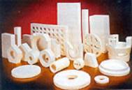
| | Figure 1. Examples of items manufactured from Hi-Por. | Manufacturing Hi-Por Ceramic Foam The manufacturing process for Hi‑Por relies on the gelation of an organic binder to stabilise the foamed structure. It should not be confused with reticulated foam, which is produced from a polyurethane skeleton. The essential components of the process are ceramic powder, organic binders, dispersing agents, a foaming agent and water. The organic binder solution provides a liquid medium, which reacts to form a strong, cross linked polymer‑water gel. This reaction traps both the ceramic powder and the water in the foamed structure. A simplified flow diagram of the manufacturing process is shown in figure 2. | 
| | Figure 2. Manufacturing steps for Hi-Por. | Structures in a Ceramic Foam There are four distinctly different structures within a foam ‑ the cells or bubbles, the struts, the windows, and the particulate microstructure. A number of cells can be seen in the left‑hand image in figure 3. These cells are formed as a result of introducing a gaseous phase into the ceramic suspension. Where these cells touch there is a tendency for the cell to change shape to maximise the packing density and for the slurry to drain from the point of contact towards the strut. A strut can be seen in the top right‑hand image in figure 3. These struts are the building blocks for the foam structure. At the point of contact between each cell a thin film of liquid exists. During gelling and binder burnout this film is removed to leave the cell windows. These are the connecting holes which join each cell and can be clearly seen in the left‑hand image in figure 3. Depending on various factors including the amount of gas introduced, these cell windows can be manipulated in size. The final structure consists of the cell walls and struts. The particulate ceramic powder can be sintered to produce either a connected highly porous microstructure or a nearly fully dense microstructure. A typical dense alumina microstructure is shown in the bottom righthand image in figure 3. | 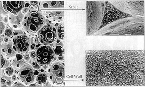
| | Figure 3. Microstructure of a ceramic foam. | Ceramic foams have so far been produced in a variety of materials with various cell sizes, densities and degree of interconnectivity. Foams are usually produced with densities between 10 and 40% of theoretical and pore sizes between 100 µm and 1 mm. The majority of the development work was carried out on a fine grained α‑alumina, before moving on to alternative materials. A few typical microstructures are shown in figure 4. The cells of the foam tend to change geometry with density ‑ the higher the density, the more spherical the cells appear, until they become isolated. As the density decreases the cells become more interconnected and begin to take on a complex geometry of struts. This type of structure can be described as a series of regular pentagonal dodecahedrons. | 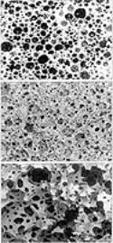
| | Figure 4. Foamed structures as a function of density. Top 1.2g.cm-3, middle 0.57g.cm-3 and bottom 0.29g.cm-3. | Forms Various ceramic foam materials can be produced to meet the design requirements most effectively, in terms of temperature, thermal shock, low thermal mass, good thermal conductivity, strength, shape or cost. For one‑off applications, Hi‑Por insulating materials can be machined, or cut to shape in the same way as fibre board, but will not create dust after cutting or heating. For larger production runs, any of the materials can be cast to complex geometries with superior definition and engineering tolerances. A variety of material choices also allows shrinkage to be considered, although this only occurs to a small extent. Applications Laboratory Furnaces Hi‑Por has already been used in laboratory furnace manufacture ‑ units are being produced that can heat from ambient to 1600°C in 15 min or less without thermal shock or any other degradation. Kiln Furniture Hi-Por kiln furniture is lightweight, so personnel are less likely to exceed health and safety weight limits when loading kilns. The low thermal mass of the furniture can give reductions in the power required when firing. Nuclear Industry The ceramic foam has also found applications in the nuclear industry ‑ conventional thermal insulation materials can be degraded by nuclear radiation, but Hi‑Por overcomes these problems. |