As stated in the article titled ‘An Introduction to a Spectrometer: The Slit’, a spectrometer is an imaging system that maps a plurality of monochromatic images of the entrance slit onto the detector plane. The articles titled, ” An Introduction to a Spectrometer: The Slit”, “An Introduction to a Spectrometer: Diffraction Grating”, and “An Introduction to a Spectrometer: The Detector,” discuss the three main configurable components of the spectrometer: the slit, the grating, and the detector.
This article will discuss how these components operate together with different optical components to create a complete system. Generally, this system is called the optical bench, or spectrograph.
Although many different possible optical bench configurations are available, the most common types are the crossed Czerny-Turner, unfolded Czerny-Turner, and concave holographic spectrographs, as shown in Figures 1, 2, and 3, respectively.
Czerny-Turner
The crossed Czerny-Turner configuration includes one plano diffraction grating and two concave mirrors (Figure 1). The focal length of mirror 1 is chosen so that it collimates the light emitted from the entrance slit and then directs the collimated beam of light onto the diffraction grating.
After the light has been diffracted and separated into its chromatic components, mirror 2 is used to focus the light dispersed from the grating onto the detector plane.
Figure 1. Crossed Czerny-Turner spectrograph
A compact, flexible spectrograph design is provided by the crossed Czerny-Turner configuration. In the case of a diffraction grating with given angular dispersion value, the focal length of the two mirrors can be designed to provide different linear dispersion values, which determines the spectral coverage for a given detector, resolution, and sensing length of the system.
When configuration geometry is optimized, the crossed Czerny-Turner spectrograph may offer a good coma correction and a flattened spectral field. However, the Czerny-Turner optical bench shows a large image aberration due to its off-axis geometry. This image aberration may widen the image width of the entrance slit by a few tens of microns.
As a result, the Czerny-Turner optical bench is primarily employed for low to medium resolution spectrometers. While this design is not meant for 2D imaging, using aspheric mirrors (such as toroidal mirrors) rather than spherical mirrors can give a certain degree of correction to the astigmatism and spherical aberration.
In order to reduce image aberrations, the Czerny-Turner optical bench is designed with an f-number of >3, which limits its throughput. In an optical system, the f-number expresses the entrance pupil diameter in terms of its effective focal length and is defined as f/# = f/D, where D is the diameter of the element and f is the focal length of the collection optic.
The light gathering power of the optical system is characterized using the f-number. The relation of the f-number with Numerical Aperture (NA) - another critical optical concept - is: f/# = 1/(2•NA), where the numerical aperture of an optical system is a dimensionless number characterizing the range of angles over which the system can emit or accept light.
Compared to a typical multimode fibers (NA ≈ 0.22), the relatively large f/# of Czerny-Turner optical benches can cause a relatively high level of stray light in the optical bench. This issue can be mitigated by unfolding the optical bench in a simple and cost-effective way (Figure 2).
This makes it possible to insert “beam blocks” into the optical path, considerably reducing the stray light, and as a result, the optical noise in the system. While this problem is not as damaging in the NIR and visible regions where there is plenty of signal and higher quantum efficiencies, it can definitely be a problem when it comes to dealing with medium to low light level UV applications. This makes the unfolded Czerny-Turner spectrograph perfect for UV applications where a compact form factor is required.
Figure 2. Unfolded Czerny-Turner spectrograph
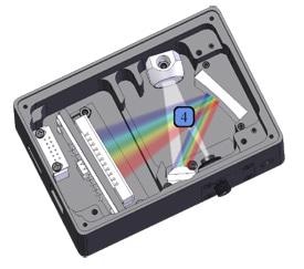
Concave Holographic
Concave holographic is the third most common optical bench, and it is based on an aberration corrected concave holographic grating (CHG). Here, the concave grating serves both as a focusing and dispersive element, which helps reduce the number of optical elements required.
As a result, both efficiency and throughput of the spectrograph are increased, making it more rugged and higher in throughput. The holographic grating technology permits correction of all image aberrations in mirror based, spherical Czerny-Turner spectrometers at a single wavelength, with good mitigation across a broad wavelength range.
Figure 3. Concave-Holographic spectrograph
Compared to a ruled grating, the holographic grating presents up to more than 10x reductions in stray light, which helps to reduce the interferences caused by unwanted light. A ruling engine produces a ruled diffraction grating that cuts grooves into the coating layer on the grating substrate (usually glass coated with a thin reflective layer) using a diamond tipped tool.
A photolithographic technique is used to produce a holographic diffraction grating. This method utilizes a holographic interference pattern. Ruled diffraction gratings, by the nature of the manufacturing process, are always produced with defects, which may consist of surface irregularities, periodic errors, and spacing errors.
All of these contribute to increased stray light and ghosting (false spectral lines caused by periodic errors). However, spacing errors, periodic errors, or surface irregularities are not produced by the optical technique used for manufacturing holographic diffraction gratings. This means, holographic gratings have considerably reduced stray light (usually 5 - 10x lower stray light compared to ruled gratings) and removed ghosts completely.
Generally, ruled gratings are used when working with low groove density, for example less than 1200 g/mm. Holographic gratings are the better choice when low stray light, high groove density, and/or concave gratings are needed. It must be noted that the maximum diffraction efficiency of concave holographic gratings is usually ~35% when compared to plano ruled gratings that can have ~80% peak efficiencies.
This information has been sourced, reviewed and adapted from materials provided by B&W Tek.
For more information on this source, please visit B&W Tek.