The process for accurately measuring solid state lighting (SSL) and LED products using an integrating sphere is described in this article. In terms of CIE 127: 2007 recommendations, the complete procedure, including absorption correction, calibration and LED measurements, is detailed.
Image Credits: Volodymyr Krasyuk/shutterstock.com
Special focus is put on the improvements in the calibration procedure using an Admesy tungsten broadband reference standard in comparison with a traditional calibration procedure. Finally, some advice is offered about ensuring precise and consistent LED measurements.
A typical LED measurement procedure with an integrating sphere includes three steps:
- Calibrating the test setup
- Absorption correction for device under test (DUT)
- Actual measurements.
Measurement Setup
To conduct rapid and precise LED and SSL measurements, an integrated sphere setup as shown in Figure 1 is suggested (CIE 127: 2007).
As seen in the figure, an integrating sphere (1) and a spectrometer (2) are connected using a fiber-optic flex cable (3) for measuring an LED (4). For absorption correction, a further correction connecting an auxiliary lamp (5) may be required.
Several reference standard lamps are required for luminous and spectral flux calibration, as shown by CIE 127. This Admesy test setup is designed for luminous flux (lm) measurements, and offers information with regards to X, Y, Z parameters as well as x,y, u’,v’, CCT, CRI and spectral distribution and dominant and peak wavelength.
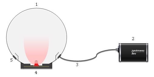
Figure 1. Integrating sphere test setup for LED measurements. Image Credit: Admesy
An integrating sphere is used for spatially distributing the unidirectional radiation emitted by the LED into homogeneous radiation.
Dependent on LED properties, an appropriate sphere must be selected. Large spheres have improved light distribution when compared to small spheres, because of the relative small geometrical errors caused by objects in the sphere. Table 1 offers an overview of the Admesy spheres and typical applications.
Table 1. Admesy integrating spheres and applications
| Model |
Diameter |
Auxiliary lamp |
Application |
Type of DUT |
| 1 |
75mm |
No |
• Production |
• Standard single LEDs |
| 2 |
150mm |
Yes |
• Production
• Laboratory |
• Standard single LEDs
• High power LEDs |
| 3 |
250mm |
Yes |
• Laboratory, CIE 127 compliant for 2π measurements |
• Standard single LEDs
• High power LEDs
• Small LED modules |
LED Measurement Procedure
Figure 2 shows three steps of LED measurement procedures, beginning with the sphere setup calibration procedure based on CIE 127 (left column) using several reference standard light sources, and the Admesy procedure (right column) using one reference standard light source with improved blue spectral response and cosine corrector.
The next step is fixture absorption correction and DUT for spheres equipped with an auxiliary lamp according to CIE 127 procedure. Finally the actual LED measurement procedure is performed.
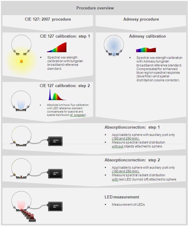
Figure 2. Overview of complete LED measurement procedure including calibration procedure as defined by CIE 127: 2007 (left column) & Admesy procedure (right column), absorption correction and measurements. Image Credit: Admesy
CIE 127 & Admesy Calibration Procedure
There are two stages in the CIE 127 LED sphere setup calibration procedure:
- Spectral wavelength calibration for spectral response of sphere
- Absolute luminous flux calibration for compensation of poor blue spectral response of tungsten reference standard and typical spatial distribution of LED.
The Admesy improved calibration procedure in a single step:
Spectral calibration with blue enhanced broadband reference standard (poor blue region compensation) and cosine corrector (spatial LED distribution).
Spectral and Spatial Distribution
According to the CIE 127, the next step is using an LED reference standard to calibrate LED setup based on their spatial and spectral distribution. Based on the broad range of variations in LEDs, according to CIE 127, it is important to maintain a large number of LED reference standards.
For each LED type that needs to be measured, a corresponding LED reference standard is needed for calibration. In terms of spectral deviations, the spectral distribution of the tungsten reference standard (Figure 3) shows comparatively low spectral intensity in the blue region when compared to longer wavelengths. Hence, in the shorter wavelength region, the signal noise ratio is non-optimal.
The measurement of white and blue LEDs, which typically have high luminous flux in this region (Figure 4) with a poor signal noise ratio, may result in inaccurate measurement results. Another reason for calibrating using an LED reference standard is because of typical spatial distribution of LEDs.
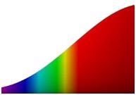
Figure 3. Spectral distribution of broadband tungsten reference standard used for CIE 127 calibration step 1. Image Credit: Admesy
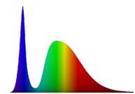
Figure 4. Spectral distribution of a (white) LED reference standard used for CIE 127 calibration step 2. Image Credit: Admesy
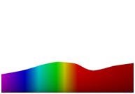
Figure 5. Spectral distribution of Admesy enhanced broadband tungsten reference standard. Image Credit: Admesy
Admesy has designed an enhanced halogen reference standard with cosine corrector and blue filter to overcome all inconveniences in both the calibration procedure and time and cost efficient LED measurements.
This reference standard combines both calibration steps of the CIE 127 recommendation. Due to the integrated blue light balancing filter, a highly balanced spectral distribution is created (Figure 5), resulting in an improved signal noise ratio in the short wavelength region. This enables precise measurements of blue and white LEDs. Furthermore, a cosine corrector allows optimal Lambertian distribution to match the spatial distribution of a broad range of LEDs. One reference standard is enough for calibrating integrating sphere setups instead of maintaining multiple reference standards.
Remarks for Measurement Procedure
High speed measurements, such as production settings, may not be as sophisticated as laboratory measurements. In order to ensure accuracy and consistency of production measurements, as recommended by CIE 127: 2007, a number of remarks are listed, which include the following:
- Control sphere for dust and dirt
- Control calibration (date) of spectrometer
- Control calibration (date) of reference standard: due to maximum lifetime
- Control stabilization time of reference standard before calibration
- Control power supplies (current, voltage, AC/ DC, waveform)
- Control measurement parameters: i.e. measurement integration time, resolution
- Control ambient temperature and humidity of test environment. CIE 127: 2007 states an ambient temperature of 25°C unless otherwise specified
- Control ambient lighting (no ambient light should enter the sphere)
- Control LED position during measurement (see examples below).
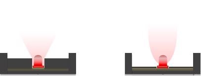
Figure 6. Undesired situation (left) light beam is affected by obstructions. Desired situation (right) light beam is not affected by any obstructions. Image Credit: Admesy
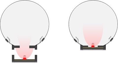
Figure 7. Generally undesired situation (left) where light from LED leaks outside the sphere. Desired situation (right) where all light emitted from LED enters the sphere. Image Credit: Admesy
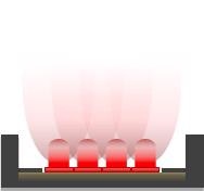
Figure 8. Components of LED and/or fixture may absorb light. Image Credit: Admesy
About Admesy
Admesy offers a broad range of test and measurement instruments focused on colour and light measurements in inline production process environments. All products are developed and produced in-house based on a long history of inline testing.
Our mission:
We provide our customers with innovative T&M solutions tailored for colour and light measurement in production processes.
Our products are innovative, compact, fast, user-friendly and robust.
Our measurement devices are developed for industrial use and combine high speed accurate measurement with a robust device with a low maintenance need. Our wide product range offers a solution for almost any measurement question.
Admesy was founded in 2006 in the Netherlands but has quickly grown into an international company serving customers all over the world from its headquarters near Maastricht, The Netherlands. Since 2013 Admesy opened an office near Seoul in Korea to quickly assist our many Asian customers.
For more information about Admesy or our products please feel free to contact us.
This information has been sourced, reviewed and adapted from materials provided by Admesy.
For more information on this source, please visit Admesy.