Sponsored by m-oemDec 2 2016
When a spectrometer is being configured for a given experiment, one of the commonly overlooked considerations is in selecting the best fiber optic cable. While there are many different factors to consider for this choice, this article focuses on two main factors - absorption and core diameter.
This article briefly reviews the function of a fiber optic cable and how it is employed to direct light into a spectrometer. It then discusses the two aforementioned characteristics and why they are important for determining the throughput of fiber optics.
Technical Details
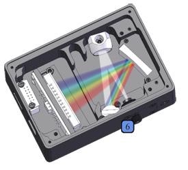
A fiber optic can be considered a “light pipe”. It can be compared to the pipes installed in a home, which directs water from one place to another, guiding it through twists and turns to the required location. In a similar fashion, fiber optics guide light waves but instead of directing light to a kitchen or bathroom, they guide the light into other optical detection systems, including spectrometers. This is accomplished by a process called total internal reflection.
In order to understand how total internal reflection is achieved, the optical property known as refraction should be looked at first. Refraction occurs because the speed of light differs based on the material it is traveling through. Therefore, when light travels from one medium to another, the angle at which it is traveling is retarded relative to the interface.
A material’s refracting power is defined as
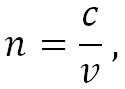 |
Equation (1) |
Where n represents the index of refraction, c is the speed of light in a vacuum, and v is the speed of light in the medium of interest. For instance, the index of refraction of water is 1.333, which shows that light travels 25% slower in water than in a vacuum, while the index of refraction of air is 1.000293, demonstrating that the speed of light in air is almost exactly the same as it is in a vacuum.
Snell’s law defines the relationship between the index of refraction and the angle at which light travels:
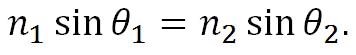 |
Equation (2) |
From this equation, it can be seen that the refracted angle (θ2) depends on the incident angle (θ1) as well as the ratio of the indices of the two materials (n1/n2). Therefore, the ratio of the indices can be controlled to engineer the refracted angle in such a way that all of the light is reflected back from the interface. This method is called total internal reflection and enables light to be contained and guided within a fiber optic.
Figure 1 shows how a fiber optic is manufactured to enable total internal reflection by using two types of glass - a higher index core and a lower index cladding - to trap the light within the fiber core and guide it via the fiber optic. The ability to collect light from one place and direct it to another makes fiber optic cables a perfect solution for coupling light into a spectrometer.
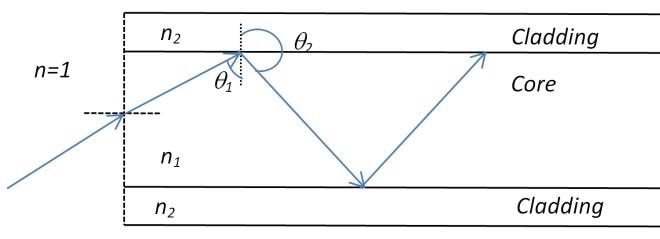
Figure 1.
Core Diameter
As all of the light in a fiber optic is collected in the core, the core diameter directly correlates to the amount of light that can be transmitted. On the basis of this principle, it would seem intuitive that a larger diameter of the core will improve the signal-to-noise ratio and sensitivity of a spectrometer.
Although this is true to some extent, there are other limiting factors that need to be taken into account when choosing the right fiber optic.
The pixel height of the detector is the first thing that needs to be considered. As described in the article, “An Introduction to a Spectrometer: The Optical Bench”, the optical bench of a spectrometer is designed to form an image of the slit onto the detector plane.
If users select a 400 µm core fiber and the detector pixels measure just 200 µm in height, 50% of the light incident on the detector will be wasted. In such situations, no benefit is obtained from having a larger core, but this issue can be resolved by adding a cylindrical lens to the optical bench in front of the detector.
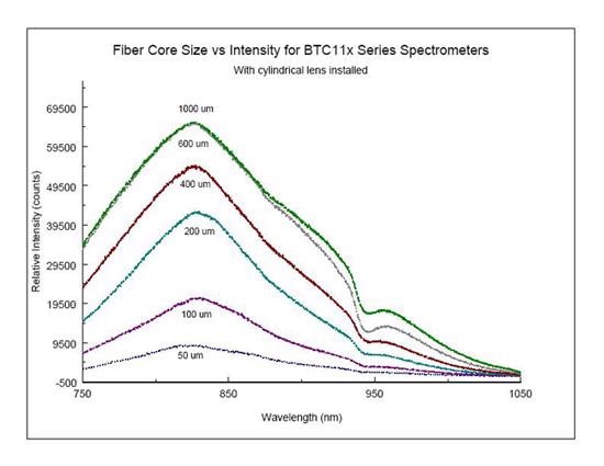
Figure 2. Signal Intensity for Various Core Diameters with a Cylindrical Lens Installed
The cylindrical lens focuses the image of the slit in the axis orthogonal to the array, without distorting the image along the axis parallel to the array in the detector plane. This enables the light from the entire core to be directed onto the detector pixel, significantly boosting the sensitivity of the overall setup. Figure 2 illustrates that this method works well for a core fiber of 600 µm.
Absorption
The absorption properties of the fiber optic are another critical factor that needs to be taken into account. If the fiber absorbs the light, the spectrometer will not be able to detect this light.
During the usual manufacturing process for fiber optics, OH- ions are inadvertently doped into the glass by the plasma torches, which are used to soften the bulb so that it can be drawn within the fibers. The presence of these ions creates extremely strong absorption bands (called water peaks) in the NIR region, which can significantly interfere with the ability to make broadband measurements via this region.
To prevent this issue when using fiber optics for NIR spectroscopy, special low OH- plasma torches should be used to manufacture fiber optics.
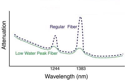
Figure 3.
Inversely, the UV spectrum has severe absorption properties that arise from a photo-chemical effect called solarization, which worsens over time with prolonged UV exposure, particularly below 290 nm.
For these reasons, close attention should be paid when choosing a fiber for a specific application. Users must select low OH- fibers optics (also known as NIR fiber optics) when operating in the NIR spectra. Standard fiber optics, also known as UV fiber optics, are also acceptable when working in the near and visible UV spectral region.

This information has been sourced, reviewed and adapted from materials provided by B&W Tek.
For more information on this source, please visit B&W Tek.