Sponsored by m-oemDec 2 2016
The basics of fiber optic cables and bundles and how they can be used to collect and direct light are discussed in ‘An Introduction to a Spectrometer: Fiber Optic Bundles’. This article will discuss how fiber optic probes can be constructed by packaging and combining fiber optics with different opto-mechanical components.
Fiber optic probes are the ideal solution for monitoring real-time kinetic reactions, analyzing large or awkwardly shaped samples, sampling in vivo, and any other application where bringing the sample to the spectrometer is difficult. Due to their flexibility and user-friendliness, fiber optic probes have become one of the most widespread tools in modern spectroscopy.
This article will discuss four of the most common fiber optic probes - reflectance probes, dark-field reflection probes, transflectance dip probes, and Raman probes.
Reflectance Probes
A reflectance probe is the most basic fiber optic probe. In its simplest form, the reflectance probe has a bifurcated fiber where the bundled or distal end is placed in a metal sheath rather than in a SMA connector (Figure 1). In this setup, the bifurcated ends can be connected to a light source, such as a fiber coupled Tungsten Halogen lamp, while the other is connected to a spectrometer.
The light from the lamp travels via the first bifurcated end to the distal end of the probe and reflects off of the sample. The reflected light will then travel from the distal end to the second bifurcated end, where it will then travel into the spectrometer for analysis.
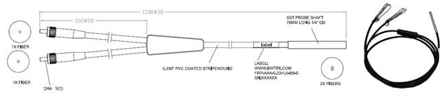
Figure 1. Fiber Optic Reflectance Probe
The system has to be calibrated by taking a reference scan before reflection data can be collected by the spectrometer. To take this reference scan, a white light reflectance standard, such as PTFE, is placed at the same geometry from the probe as will be used in the actual measurement.
This will enable the spectrometer to determine which wavelengths of light are reflected and which are absorbed by measuring the ratio between a “perfect” white light reflector and the sample of interest.
There are two standard geometries that are employed when measuring reflection: 0° and 45° normal to the sample. The probe will pick up the specular (mirror like) component of the reflected light and the diffuse component when measuring at 0°.
However, most of the specular light is not collected by the probe when measured at 45°. This is a significant consideration in applications such as colorimetry and NIR spectroscopy, where the specular component can distort the spectrum and skew the results.
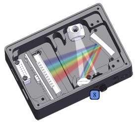
Employing a round-to-slit fiber optic bundle is a more complex method of designing reflectance probes. This is a common method to overcome the issue of weak photon energy in the NIR. This method is applied in several reflection probes designed to work in the NIR; a 6-around-1 configuration is employed on the distal end and 6 fibers are stacked on the bifurcated end attached to the spectrometer.
As shown in Figure 2, the 6 outer fibers are going to the slit configuration on the spectrometer, while the center fiber connects to the light source in the other bifurcated end.
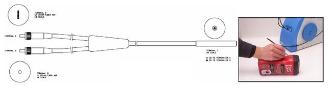
Figure 2. Fiber Optic Reflection Probe with Slit-to-Bundle Configuration
To increase the spectral range over which the reflection data is collected, reflectance probes can also be scaled up to trifurcated and quadfurcated designs.
Dark Field Reflectance Probes
Specular reflection does not contain any useful information for NIR spectroscopy, but it can typically be removed by measuring the sample at a 45° angle. However, dark-field illumination – a method borrowed from microscopy – can be employed if the sample cannot be measured at a 45° angle, such as when working in a production or field setting.
The diffusely reflected light is subsequently collected by a bundle of 7 fibers in the center of the probe, which directs the light to the spectrometer in a slit configuration (Figure 3). To redirect the light away from the center fiber bundle, a lens is used at the distal end of the probe, further reducing the specular components of the light.
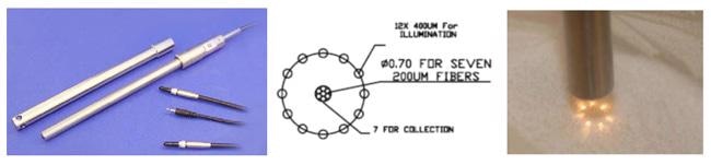
Figure 3. Dark-Field Fiber Optic Probe
Transflectance Dip Probes
Reflection probes can be used to measure liquids, even though they are primarily designed to measure solids. A dip probe is generally the probe of choice while measuring liquid samples, as it can be submerged into the sample, allowing for kinetic data to be collected.
A fiber dip probe is similar to a reflection probe in design, although special effort is taken to guarantee that it is inert and liquid tight. The main functional difference is the presence of a cavity, which fills with the liquid sample when immersed.
To reflect the transmitted light back through the sample and into the collection fiber, this cavity is equipped with an optically transparent window placed at the distal end of the fiber and a small mirror placed at the bottom of the cavity (Figure 4).
This setup is commonly known as a transflectance, as it combines transmission and reflection, doubling the optical path length.
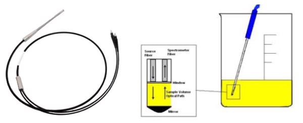
Figure 4. Fiber Optic Transflectance Dip Probe
It must be noted that a dark-field reflectance probe configuration can also be used to make transflectance measurements. An adaptor can be placed over the dark-field probe to allow for transflectance measurements in slurries and liquids (Figure 3).
Raman Probes
The Raman probe is used to measure the inelastic scattering of light off of a sample. Raman scattering is a nonlinear effect that results in the shift in wavelength from a known monochromatic source. This shift is equal to the vibrational frequency of the molecular bonds in the material.
Consequently, a Raman probe must have the capacity to direct and focus the monochromatic excitation source (typically a laser) to the sample, collecting the scattered light and then directing it to the spectrometer. A typical design for a Raman probe can be seen in Figure 5.
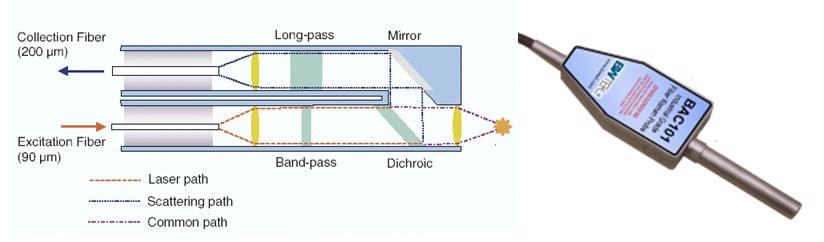
Figure 5. Typical Design of a Raman Probe
A narrow band-pass filter is placed in the optical path of the excitation source before it reaches the sample as a pure signal is highly critical to Raman spectroscopy. It must be noted that the signal must be collected at a 0° angle normal to the sample as the Raman Effect is extremely weak.
This leads to interference from specular reflections, which is referred to as Rayleigh scattering in this case. Therefore, it is important to filter the collected signal using a long pass filter before it is directed to the spectrometer.
The Raman probe is an perfect example of how fiber optics can be coupled with other optical components, enabling simple and flexible measurement of even the most difficult spectroscopy.

This information has been sourced, reviewed and adapted from materials provided by B&W Tek.
For more information on this source, please visit B&W Tek.