Active systems can actually take several different forms, although "position" and "acceleration" servos have been alluded too. Additionally, the servo’s basic performance can be increased using feedforward. This article describes the most common configurations and their relative merits in the following sections.
Inertial Feedback
The inertial feedback system is the most popular type of active cancelation system (Figure 1). The pneumatic isolators have been designed as a simple spring. Neglecting the ground motion sensor and the feedforward input, the feedback path includes a filter, seismometer, and force actuator (such as a loudspeaker “voice coil”).
The seismometer is capable of measuring the displacement between its test mass and the isolated payload, filtering the signal, and then applying a force to the payload in such a way that this displacement (X1 - X2) becomes constant, thereby negating the seismometer output.
The only force acting on the test mass arises from the compression of its spring, and the compression is servoed to be constant (X1 - X2  0), and it follows that the test is actively isolated. Similarly, the isolated payload must also be isolated from vibration as it is being forced to track the test mass. The details of this form of servo are available in several references.*
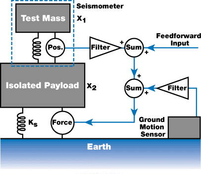
Figure 1. The basic inertial feedback loop uses a payload sensor and a force actuator, such as a loudspeaker “voice coil,” to affect the feedback. Feedforward can be added to the loop at several points.
The servo bandwidth always limits the performance of this type of system. Due to structural resonances in the isolated payload, the bandwidth in practical systems is limited to 10 - 40 Hz (generally towards the low end of this range). This kind of system is also “AC coupled” because the seismometer lacks a “DC” response.
Therefore, the servos possess two unity gain frequencies – usually at 0.1 and 20 Hz. Consequently, the servo reaches a maximum gain of about 20 - 40 dB at ~2 Hz – which is the natural frequency of the passive spring mount for the system. At the ~0.1 and ~20 Hz unity gain frequencies, the system’s closed-loop response has two new resonances.
Since these systems have a small bandwidth (just about two decades in frequency), the gain is not very high except at the natural (open-loop) resonant frequency of the payload. The high gain suppresses that resonance.
For this reason, these systems can be considered as inertial damping systems, which have the property of damping the main resonance of the system without affecting the vibration isolation performance. (This resonance can also be damped by passive damping but this considerably increases vibration feedthrough from the ground.)
PZT-Based Systems
The concept of a “quiet pier” isolator such as TMC’s line of active isolators (Patent Nos. 5,660,255 and 5,823,307) is illustrated in Figure 2. It contains an intermediate mass, which is hard mounted to the floor through a piezoelectric transducer (PZT).
A geophone is mounted to this, and it's signal is fed back to the PZT in a wide-bandwidth servo loop. This creates a “quiet pier” for supporting the payload to be isolated. A 20 Hz elastomer mount provides isolation at frequencies that are above the active bandwidth of servo.
In addition, this elastomer prevents the piers from “talking” to each other through the payload (it is important that a payload rests on a few independent quiet piers). This system comes with certain unique advantages and disadvantages.
The STACIS® system has excellent vibration isolation performance. In fact, it is among the best in the 0.6 - 20 Hz frequency range, subject to certain limitations. Compared to inertial feedback systems, the STACIS® system does not require much adjustment and the elastomer mount makes it all but completely immune to structural resonances in the payload.
As the system is “hard mounted” to the floor through the 20 Hz elastomers, payload alignment with external equipment (docking) is not a major problem. The settling time is very good as the system’s response to an external force (a moving stage) is that of the 20 Hz elastomer mount. This is similar to the best inertial feedback systems.
Also, due to the stiffness of the elastomer mount, the STACIS® system becomes almost immune to forces, including room air currents, that are directly applied to the payload and allow it to support extremely high center-of-gravity payloads.
The STACIS® system can support, and is compatible with, tools that integrate all types of built-in active or passive pneumatic vibration isolation system.
Unfortunately, the PZT has a range of motion which is restricted (around 20 - 25 µm). As a result, the servo saturates and “unlocks” when the floor motion crosses this peak-to-peak amplitude. Fortunately, the floor motion never crosses this amplitude in most environments.
In order to acquire a good vibration isolation characteristic, ~0.6 to ~200 Hz is the active bandwidth for the PZT servo. This high bandwidth can only be achieved when the isolator is supported by a very rigid floor. This is required by the isolator as it relies on the intermediate mass moving an amount that is proportional to the PZT voltage up to a few hundred Hz. This may not be true if the floor has a resonance within the active bandwidth.
Resonances in most floors are well below 200 Hz, but this is acceptable provided that the floor is massive enough for its resonance not to be considerably driven by the servo. The correct form of the floor specification becomes floor compliance, inin/lbf (or µm/N).
The STACIS® system generally must be mounted directly on a concrete floor, and it will work in welded steel frames or on raised floors only when the support frame is extremely rigid. “Building sway” is another problem which is referred to the motion at the top of a building induced by wind. Usually, this is more than 25 mm on upper floors, allowing the system to saturate if used in upper stories (based on the aspect ratio and construction of the building).
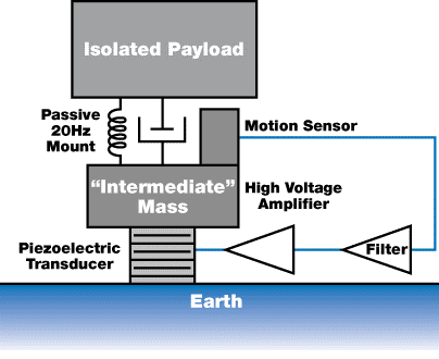
Figure 2. This method involves quieting a small “intermediate mass” with a high- bandwidth servo, then mounting the main payload on that “quiet pier” with a passive 20 Hz rubber mount.
Vibration Critical Applications
Vibration critical applications are actually in the minority. To put it simply, the number of applications that require better vibration isolation than provided by a passive system, is very small.
TMC’s Passive vibration isolation systems can effectively suppress ground noise at frequencies above a few Hz. Only two types of applications are available where the vibration isolation performance of a passive isolator is an issue.
First, the ground noise level may be so high that an instrument that operates in most environments becomes sensitive to ground noise. This only occurs in tall buildings where building sway becomes a critical issue or in buildings that have very weak floors. This is a unique situation, because most equipment (for example semiconductor inspection machines) often come with a “floor spec” that is generally not overlooked by vendors.
The second type of application are those with the highest degree of intrinsic sensitivity. Atomic force and scanning tunneling microscopes (AFMs and STMs) are some of the key examples. These applications are sensitive to the smallest payload vibrations and have atomic scale resolutions.
In both of these situations, the isolation performance of passive mounts is often sufficient, barring the frequency range from approximately 0.7 Hz to 3 Hz where a passive mount amplifies the ground motion. This is a convenient coincidence, because active systems such as the inertial feedback scheme can effectively remove this resonant amplification.
An active vibration cancelation system should be avoided unless users are sure that their applications have a vibration isolation problem that can't be solved with passive isolators. Settling time seen in most semiconductor equipment today is a different issue.
The Problems with Inertial Feedback
Although inertial feedback systems can be used to reduce the settling time and enhance vibration isolation performance, they have several significant disadvantages. Implementing a horizontal inertial feedback system is largely restricted by the tilt to horizontal coupling problem. In addition, these systems, except for PZT-based systems, have relatively poor position settling times.
The response of a payload to an external disturbance is illustrated in Figure 3. Based on a model of an idealized 1-DOF system, the response of a payload is only intended to qualitatively show the performance of a multi-DOF system.
The same active system is represented by both curves, except the first curve plots the ratio of displacement to the applied force, and the second one plots the ratio of acceleration to the applied force, both as a function of frequency. The only variation is that the first graph has been multiplied by two powers of frequency to create the second one.
The curves respectively show what an accelerometer and a position sensor would measure as this system was disturbed. It must be noted that the magnitude scales on these graphs have a random origin and should only be used for reference purposes.
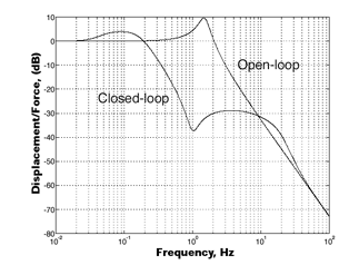
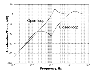
Figure 3. The curves show that the position response is dominated by a low- frequency resonance, while the acceleration response is dominated by a high-frequency peak. Note that the peak in the open-loop response is the same.
The curves demonstrate that a low-frequency resonance dominates the position response, while a high-frequency peak dominates the acceleration response. This result is counter-intuitive because the peak in the open-loop (purely passive) response is at the same frequency in either case.
This provides two benefits. First, this system effectively suppresses the open-loop resonance in the system. It even provides a considerable amount of extra isolation in the 0.5 - 5 Hz frequency range. The second benefit is that a well-damped resonance dominates the acceleration curve at around 20 Hz. If we presume the amplitude of the acceleration decays as:
Amplitude = A0 x e-t/τ
where A0 represents the initial amplitude and τ = Q/( πv). If the quality factor Q is approximately 2, then τ ≈ 32 ms which is relatively good. For payloads that are sensitive to acceleration (which most are), the system’s settling time will be enhanced by an order of magnitude by this servo.
The issue associated with this system is shown in the first set of curves, indicating that the position response is dominated by a peak at ~0.1 Hz. Assuming the same Q as above, this would mean the decay constant t is about 6.5 seconds. Despite the fact that the servo has been designed with a large phase margin to get the Q down to 2, the peak’s low frequency means it takes a long time to settle in position.
While payloads are highly sensitive to accelerations, there are two distinct cases where a long position settling time presents a major issue.
A long position settling time in the pitch or roll DOF of a payload can appear like a horizontal acceleration. This is due to Einstein’s Principle of Equivalence: As a payload tips, the direction that gravity acts on the payload changes from fully vertical to some small angle off vertical.
By principle, this is identical to having a level payload which is being accelerated by an amount equal to the tip angle (in radians) x g. To put it simply, each mrad of tilt turns into a mg of horizontal acceleration. Electron microscopes and many instruments are sensitive to this.
Docking the payload is another major issue. This is a common process where the payload has to be periodically positioned relative to an off-board object with extreme accuracy – usually 20 to 200 mm. An inertial feedback system will take an extremely long time to position to this level. Two possible solutions are available for this.
The first approach is to run the servo at a lower gain setting, compromising some isolation performance (which may not be required) for an improved position settling time. The second approach is to turn off the servo for docking. However, servos do not like to be turned on and off quickly – particularly when their nominal gain is as high as the one shown here.
When Will You Need an Active System?
Determining the need for an active isolation system can vary based on whether you have a settling time or vibration critical application. Both can be complex, and in either case, the system’s susceptibility to vibrational noise needs to be known.
When it comes to vibration critical applications, it is not enough to simply ask whether the system will work. If the performance is insufficient or the system does not work with passive systems, then the source of the problem has to be identified.
It may be obvious for AFM/STM type applications. The stylus’ raw output is dominated by a 1.5 Hz noise and that, in turn, is correlated with the payload motion, and you know your isolators have their resonance at that frequency. It may be less clear at other times.
For instance, you may see a 20 Hz peak in your instrument, and that correlates with the noise on the payload – but it is not clear whether it is coming from the ground.
In buildings, many HVAC systems use huge fans that function in this frequency range. If they do, they generate ground noise as well as acoustic noise which are correlated with the noise on the payload. So what is the source of the problem? Acoustics or ground noise? This can be difficult to tell.
However, it must be remembered that if your issue is at 20 Hz, then inertial feedback active systems will be useless because they lack the loop gain at that frequency. STACIS® and other such PZT-based isolators may provide the only solution in this frequency range.
Settling time critical applications is much simpler. There are three steps to determine if you need an active system (which we assume to be feedforward only):
- Step one: Determine the critical acceleration level for the process. This can be done simply by moving the stage and waiting different amounts of time prior to making a measurement. If the duration of wait and the acceleration level of the payload is known following the stage stops, then this number can be derived. For the latest instrument, it can be very difficult to determine the critical acceleration level, and calculations, estimates, and modeling may need to be relied on.
- Step two: Estimate the payload’s initial acceleration level by multiplying the stage acceleration by the ratio of the stage mass to total isolated payload mass.
- Step three: The numbers from steps one and two should be compared. Any TMC passive system should work if the critical acceleration level is above the initial payload reaction. However, if the critical acceleration level is below the initial payload reaction, then the ratio of the initial has to be compared to critical acceleration levels, and Equation 1 should be used to determine whether the system can settle fast enough.
- If the allowed settling time is not enough to get the required attenuation, then a system with higher passive damping could be used. The MaxDamp® isolators offered by TMC have a decay rate up to five times faster than traditional pneumatic isolators (a Q-factor five times lower). While this does sacrifice some vibration isolation, it is often a good tradeoff.
- If the MaxDamp® isolator does not work, then an active system can be used (passive isolation systems have run out of free parameters to solve the problem).
Certain extreme examples are available that can determine the need rapidly. For instance, an active system is required if the critical level is below the initial payload acceleration and a "zero” settling time is desired. However, the instrument will need to be re-designed or enable for a non-zero settling time if the ratio of the initial to critical level is more than 10 (with “zero” time). Active systems are not the ultimate solutions and cannot solve all the problems.
Conclusion
Moore’s Law** has created a challenge that requires better collaboration between systems engineers, semiconductor tool manufacturers, stage manufacturers, and integrators. There also needs to be a major improvement in the awareness of the problem. This is a legacy of the former days where “blind integration” of systems was found to be adequate.
Given that the conflict with vibration isolation systems and high system throughputs are critical, system engineers must shift their design goals. Also, active systems can only enhance the systems’ performance by a certain factor. If the design methods are not changed, even active systems will not work in the near future.
This will be very unfortunate because there is no advanced technology that one can turn to. The specifications seen by TMC cannot be met even with the most optimistic assumptions about active system performance.
Active systems are quite expensive. The costs of these systems are pushed by PZT or magnetic actuators and other similar components. The cost of their materials contributes to their high prices (piezoelectric ceramics rare earth or NdFeB magnets). Power amplifiers can be expensive.
If cost is a consideration, it must be remembered that there is no such thing as an incremental active solution. The active system, if required, must be able to match the forces produced by your stage motions. A less capable system will simply not work.
TMC continues to improve active isolation systems. The company aims to make these systems more reliable, easier to configure, install, and maintain, and also to make them self-configuring whenever possible. This will bring down engineering times, system costs, and expedite the production of systems.
* See for example, P.G. Nelson, Rev. Sci. Instrum., 62, p.2069 (1991).
** Gordon Moore, co-founder of Intel Corp., has pointed out that the density of semiconductors (in terms of transistors/area) has roughly doubled every 18 months, on average, since the very earliest days of commercial semiconductor manufacturing (even 1960 or earlier!).
This information has been sourced, reviewed and adapted from materials provided by TMC.
For more information on this source, please visit TMC.