The rule of thumb “no active-on-active” states that a machine incorporating active vibration isolation (internally) cannot be mounted on a platform using active vibration control. This rule is incorrect, as it is only applicable to specific types of active vibration isolation systems.
The “no active-on-active” rule exists because it is possible for one active isolation system to influence another system. This is enabled by two mechanisms. The first one involves coupling the two mass-spring systems to produce another system with different and complex ‘normal mode’ frequencies, that is, the frequencies in which the system oscillates post-disturbance.
This alters the control system’s loop transfer functions, and results in non-optimized or unstable performance. In this mechanism, two systems of comparable stiffnesses are coupled, and not a coupling of the control loops in the two systems.
This can also be achieved by keeping a tool with an active pneumatic system on a passive pneumatic platform. The STACIS™ active isolation system prevents this by featuring a stiffness which is more than 100 times higher than that of a typical pneumatic system.
The other mechanism is based on actual coupling of the system in the supporting platform and the control system internal to the tool. Figure 1 shows two electro-pneumatic active isolation systems placed on top of one another (simplified to one degree-of-freedom).
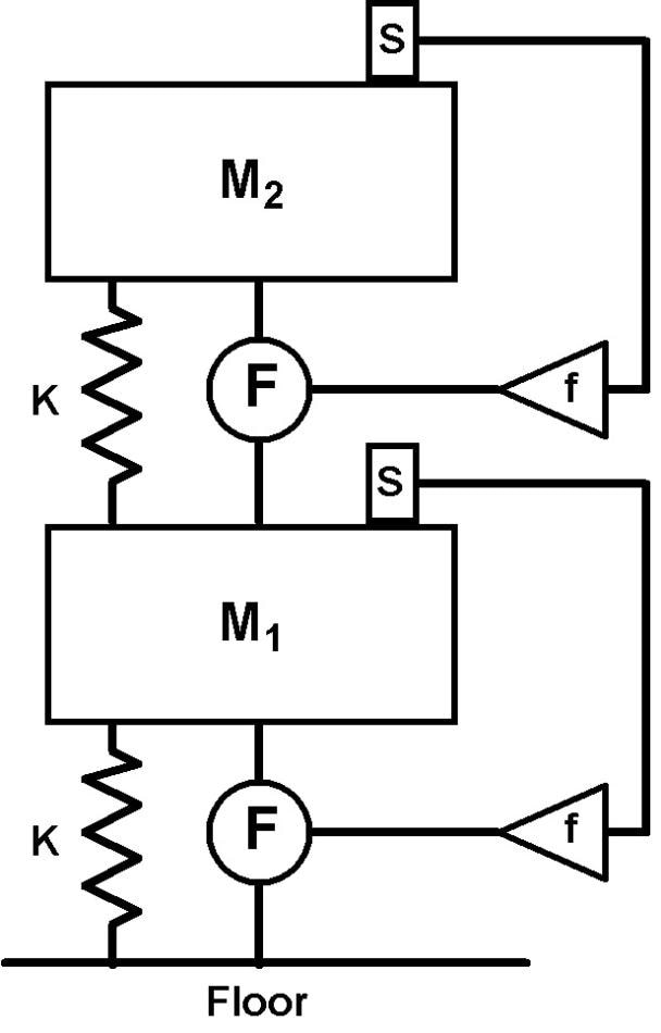
Figure 1
Here, each system holds a mass (M1 & M2) on a (pneumatic) spring (K). M1 represents the subfloor platform for the tool and the frame of the tool. The internally isolated payload in the tool is represented by M2. The two masses are almost equal, as are the springs.
Each of the active systems has a compensation system and amplifier (f), a force actuator (F), and a sensor (s). In this second mechanism, an undesirable or unstable control loop is formed, involving the two (nominally independent) systems. For instance, a disturbance on M2 triggers a signal in the top sensor resulting in the generation of a force in the top actuator.
However, the top actuator pushes against the low mass M1 to cause a a signal to be generated in the lower sensor, and a response in the lower actuator. This leads to transmission of a force to the M2 through its support spring, forming a loop. Such loops may be stable, but they are always undesirable.
The STACIS™ active isolation system avoids such problems by decoupling the first and second control loops, as illustrated in Figure 2:
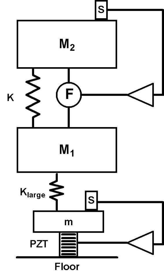
Figure 2
In Figure 2, M1, M2, and K represent the same components as before, but the bottom spring, actuator, and sensor are substituted by a STACIS™ piezoelectric isolation system. It is made up of a sensor (s) placed on a small mass (m) – typically only a few kilograms in weight.
The sensor’s output is filtered and drives a PZT stack which cancels the sensors output in a high-bandwidth servo (usually 200 Hz). The mass M1 is held by a spring (Klarge) which is more than 100 times stiffer than the spring (K).
The STACIS™ system does not affect the tool’s internal active isolation system. The normal vibrational modes for the mass M2 are not changed because the (series) stiffness is dominated by K (Klarge > > K). Due to this, the loop transfer functions of the tool’s control system are not changed, and its performance is not affected.
The resonant frequency of the tool and platform on the STACIS™ isolator (Klarge) is about 20 Hz, which is in the comparable range of the lowest resonances in most frame structures and many floor structures.
Additionally, the tool’s active system does not affect the STACIS™ isolation system, and this is because of the high stiffness of the PZT stacks (usually several hundred million N/m).
Force transmitted to (m) via (Klarge) does not result in the motion of small mass. This eliminates any potential ‘active on active’ feedback loops, and provides the STACIS™ with a ‘plug-and-play’ feature; the system requires only a little or no adjustment in most installations.2
Test Results
To show the ability of STACIS™ to back active pneumatic isolation systems, an ElectroDamp™ II3 system was set up on top of a platform held by STACIS™ isolators, as seen in Figure 3.
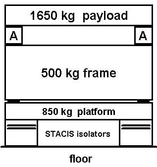
Figure 3
ElectroDamp™ II is a six degree-of-freedom, high performance active isolation system centered on payload-mounted vibration sensors, a DSP-based control system, and high-force linear motors. It can measure payload motion with the sensors, and provides a compensating force to enhance vibration isolation and damping effect (as shown in Figures 1 & 2).
Additionally, it can use information from stage motion controllers to apply multi-axis feedforward signals. It is used in semiconductor manufacturing equipment, and is commonly found in electro-pneumatic isolation systems. Figure 4 is a photograph of the setup depicted in Figure 3.
In Figure 4, the ElectroDamp™ active isolators are shown at (A). The entire system covers an area of about 1.5 m2. The isolated payload (B) is a steel casting which weighs 1650 kg. The frame (C) is of a welded steel construction, and weighs about 500 kg and measures 1 m in height.
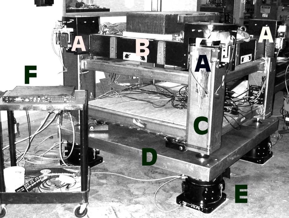
Figure 4
A standard TMC sub-floor platform (D) consisting of an epoxy-bonded lamination of steel plates and stiff damping layer in a stainless steel casing is below the system. The platform weighs about 850 kg. The entire system on a poured concrete floor is supported by four medium-capacity STACIS™ isolators (E). The STACIS™ DSP-based controller is shown at (F).
After system set up, the STACIS™ and ElectroDamp™ systems were switched on. The systems did not require adjustments to be functional or to satisfy specifications. As a part of standard installation procedure, the ElectroDamp™ system’s Auto-Tuning algorithm was then activated to optimize the system.
The auto tuning ran without any problem, and carried out only small gain adjustments (of the order of a few dB). Such modest levels of gain adjustments are typical of any installation.
In order to know how insensitive the ElectroDamp™ is to the existence of the STACIS™ system, it is necessary to consider the open loop transfer functions in the ElectroDamp™ system. The transfer functions are measured first by ‘breaking’ the control system loop, injecting a test signal at the ‘in’ portion of the break, and then measuring the phase and magnitude of the response at the ‘out’ portion of the break.
These curves are useful to servo engineers for determining dynamic response and stability of the system. Figures 5 through 7 illustrate the open loop transfer functions for the X, Z, and Theta-X (rotation about the horizontal X-axis) degrees-of-freedom.
In all of the graphs, the curve marked (A) is the loop transfer function measured with the ElectroDamp™ frame which was placed on the concrete floor. The curves marked (B) represent the loop transfer functions measured with the system placed on the STACIS™ platform as shown in Figures 3 and 4, with STACIS™ active (on).
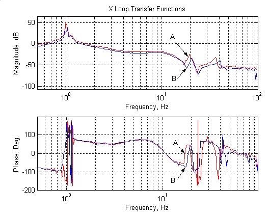
Figure 5
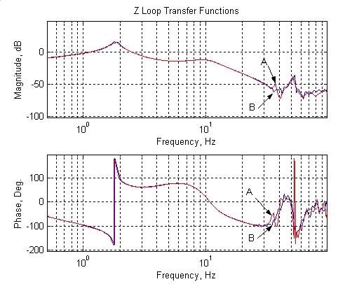
Figure 6
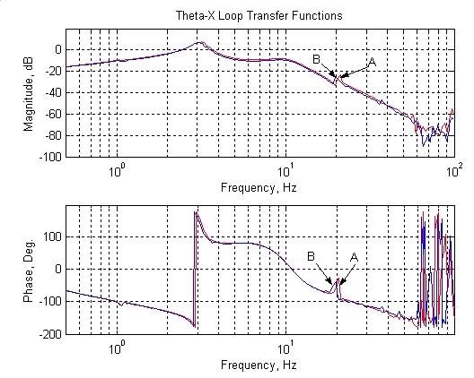
Figure 7
In most regions, the (A) and (B) curves are too close to distinguish them. The frequency and magnitude of the primary mode of oscillation in the DOFs were not changed even after mounting the ElectroDamp™ system on the STACIS™ platform. The resonances noticeable from 20 - 50 Hz are caused by the welded frame and casting.
It is critical to remember what the loop transfer functions are measuring. It must be known that a force is applied to the payload by linear motors fixed to the base frame, and the vibration sensors on the payload measure the response to that force.
The curves demonstrate that, irrespective of the details of the control system, the frequency response is unaffected by STACIS™. Specifically, any control system operating in the bandwidth of 0.5 - 100 Hz will have no change in its frequency response due to STACIS.
This argument is also applicable to systems that make use of feedforward to nullify payload reactions to stage motions. The force applied in the feedforward system causes the same payload reaction, irrespective of the existence of STACIS™.
This is a more rigorous requirement than what is needed. In a optimally designed feedforward system, the vector forces produced by stage accelerations are nullified by forces produced by the linear motors. If this nullification is complete, then it doesn't matter what the payload dynamics are or what the frequency response is. This results in no motion.
Benefits of STACIS™ System
STACIS™ enables the tool manufacturer to install equipment in locations that are otherwise too noisy for the tool. To demonstrate this, Figure 8 displays the vertical vibration transfer function for TMC’s ElectroDamp™ system installed on a subfloor platform mounted on STACIS™, as depicted in Figures 3 and 4.
Instead of placing the STACIS™ system on the floor, the system was placed on a second floor platform, weighing 1,730 kg, supported by high-capacity STACIS™ isolators. The second system was used in the testing for providing a controlled floor excitation of about 1 micron amplitude.
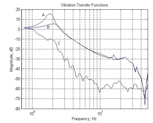
Figure 8
In Figure 8, curve (A) is the vibration transfer function for the system when the ElectroDamp™ and STACIS™ systems are turned off (passive pneumatic isolators only). Curve (B) is the vibration transfer function with only the ElectroDamp™ functioning4, and (C) is when the two active systems are running. The measurements were made using Kinemetrics model SS-1 seismometers with 100x preamplifiers.
As can be seen by the measurement, the isolation at 10 Hz is increased by about 30 dB by STACIS™, with a total attenuation of about 60 dB (the noise in (C) is a result of the very low levels being measured – approximately 1 nm). In the 2 Hz range (where several buildings have high levels of noise), the system provides 10 dB of isolation, which is an order of magnitude better than when only an air isolator is used (curve (A)).
Conclusion
This data conclusively shows that ‘soft mount’ active isolation systems using linear motors to improve passive pneumatic isolation systems’ performance can be mounted on STACIS™-based platforms without their performance being affected.
In addition, the STACIS™ isolation system is not sensitive to active systems mounted on top of it, since the dynamics of its control loop is determined by the stiffness of the supporting floor and PZT actuators, whose stiffness is much more than that of any of the elements in the active pneumatic system. Klarge also helps to isolate the STACIS™ control system from forces produced on the payload.
STACIS™ allows more flexibility to tool makers and end users in the installation of tools that use active systems. For instance, several tools have floor vibration criteria for the installation site that need to be satisfied for the tool to meet its performance specification.
If a site is not able to meet this specification, the tool can be moved to another site, or installed on a sub-floor isolation system. Unlike ‘soft mount’ isolation systems, STACIS™ can be used in such situations without causing any adverse effects on the tool.
References
1 US Patent Number 5,660,255
2 Some installations on soft floors require minor gain adjustments to the STACIS™ loop gain.
3 US Patent Number Re. 33,937
4 The gain in this ElectroDamp™ system is set to optimize settling time and payload positioning, not vibration isolation.

This information has been sourced, reviewed and adapted from materials provided by TMC.
For more information on this source, please visit TMC.