| Pulsed neutron strain scanning is a powerful non-destructive technique capable of measuring stress fields deep within engineering components. Now a team from the Open University and the ISIS neutron source has extended the method, with the installation of a purpose-built Instron test rig on its ENGIN instrument. This allows the application of uniaxial loads to samples in situ - while neutron measurements are being made. Neutron Strain Scattering Neutron strain scanning was developed in the early 1980’s to allow the non-destructive determination of the stress state centimetres below the surface of a component. Similar to the much less penetrating x-ray technique, neutron strain scanning uses the crystal lattice as an ‘atomic strain gauge’. When the atomic lattice planes are stressed the separation between them changes. Because this separation can be determined from the diffraction pattern of a beam of neutrons from the sample, as described by Bragg’s equation, the stress is detected as a shift in the position of the diffraction peaks. This is a direct measure of the elastic component of the strain. How the Technique Works Stress and elastic strain are linked through a material’s elastic constants. Neutron diffraction measures the elastic strain within a defined gauge volume, so it is possible to calculate the stress in that volume provided the material’s elastic constants are known. To determine the full three-dimensional stress the elastic strain must be measured along a number of directions. If the principal strain directions within the body are known, then a minimum of three orthogonal directions must be determined. Otherwise, measurements along further directions are required. Advantages of the Neutron Strain Scattering Technique ENGIN is the world’s first purpose-designed pulsed neutron strain scanner. Its development at ISIS in Oxfordshire, the world’s most powerful pulsed neutron source, has provided the UK with a unique facility. ENGIN possesses key advantages over more conventional stress measurement techniques -these include the ability to make non-destructive, non-contacting strain measurements in nearly all crystalline materials. Sub-surface, ‘bulk’ material properties can be measured - impossible with any other technique - and simultaneous and separate measurement of the strain in multiple phases, and multiple directions within a sample, is also possible. Measuring Neutron Strain Scattering A schematic of the ENGIN instrument, as it is used for measurements of positional variation of stress, is shown in figure 1. A measurement volume is defined within a sample, by means of incident slits and radial collimation of the outgoing beam. The sample is placed on an x-y-z-w translation table, on which it can be moved relative to the incoming neutron beam, allowing the scanning of the defined measurement volume within the sample. | 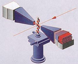
| | Figure 1. Schematic of the ENGIN system. Arrow indicated path of neutron beam passing through the sample and between detectors on either side of the sample located on adjustable stage. | Taking Measurements under Load Adding a purpose-built hydraulic stress rig to the ENGIN instrument means that external loads can be applied to samples while neutron measurements are being carried out. The stress rig was designed to minimise weight and allow full access to the incident and diffracted neutron beams. With the stress rig in place ENGIN can be used to probe the internal stresses developing in materials as they are deforming, or to map the strain distributions inside components under load. An example of the former use is given in figure 2, which charts the typical development of internal strain during a tensile test on an Al/SiC metal matrix composite. | 
| | Figure 2. Cumulative internal strain in a 17% SiC/Al MMC | Case Study – Strain Development in a 17% SiC/Al MMC Initially, the strain in the two phases increases linearly with applied load. The gradients of the two lines are different due to the different stiffnesses of the Al and SiC. After yielding begins the amount of elastic strain in the Al matrix increases only slowly, while that in the SiC reinforcement increases rather more rapidly due to the transfer of load to that phase. So, for a given increment in macroscopic load, the reinforcement now bears a larger fraction of that load than does the matrix. Neutron measurements such as these play a vital role in understanding and modelling the micro-mechanical behaviour of composites. Case Study – Aircraft Fastener Systems The optimisation of fastener systems in aircraft structures requires comparative fatigue data, generated on laboratory joint systems, which accurately reproduce the main joint variables of secondary bending and load transfer. Pulsed neutron strain scanning has been used to make non-destructive measurements of the internal strain distribution deep within a complex joint under both zero and 30kN loads, figure 3. The test section of the joint contains a single shear connection consisting of interference fasteners in a cold expanded hole. It is important to know what effect these fastener conditions have on the load transfer and secondary bending characteristics of the joint, as they may significantly affect the fatigue endurance. | 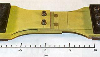
| | Figure 3. Complex joint system. | Figure 4 shows the strain distributions measured on the section tangential to one of these fasteners. It provides dramatic confirmation of the excellence of this fastener system - the hole has been shielded from deleterious tensile strains under operational loading. That is, the strains around the hole have remained compressive even when the joint is under 30kN tensile load. | 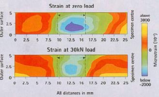
| | Figure 4. Strain distribution adjacent to each fastener hole for the joint in figure 3. | Future Developments Pulsed neutron strain scanning offers insights into many material and engineering problems that are unobtainable using other means. The ability to alter the applied stress and simultaneously vary the measurement position within a specimen opens the door to many exciting opportunities for solving hitherto intractable problems. Further development of pulsed neutron strain scanning at ISIS is already underway through a £2.5 million project funded under the EPSRC’s Engineering Instrument Development Initiative to develop ENGIN-X, a next-generation neutron strain scanner. ENGIN-X will perform 10 times better than the current technology, and will reduce measurement times to as little as 30 seconds per point. |