Sponsored by HORIBAJun 14 2018
Solid oxide fuel cells (SOFCs) have the potential to lessen our reliance on coal and oil for energy. They are clean, quiet, and efficient. The most important part of these cells are the unique mixtures of polycrystalline ceramic materials, each having a particular set of structural and electrochemical requirements, the performance of which can be tailored by controlling the chemical and physical properties of the starting powders.
Particle size is an important property of powders and cell performance. Laser diffraction particle size analysis is an ideal method of controlling and monitoring the particle size of these powders during powder synthesis and component fabrication.
Introduction
SOFC is a solid-state electrochemical cell whose operation temperature ranges between 600 and 1000 °C. Ceramics are greatly used in the construction of the cell components because of the high temperatures required for the activation of conduction.
As shown in Figure 1, the electrolyte is made up of a dense ceramic layer, usually yttria-stabilized zirconia (YSZ), which acts a medium for the transport of oxygen ions and is 10 µm or less in thickness. The cathode consists of an electronically conducting microporous ceramic layer. Newer cathodes are made of mixed ionic/electronic conductors which increases their ability to ionize oxygen in the air, providing oxygen ions for conduction.
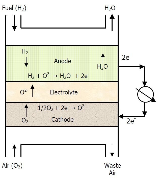
Figure 1
For anodes, a commonly used material is a NiO-YSZ composite and has a porous microstructure to allow hydrogen flow to the anode/electrolyte interface. It must be electronically conductive and should be robust enough to withstand a severely reducing environment.
Electrical interconnections between the cells in a SOFC are also made of ceramic materials, which must be electronically conducting and chemically stable in oxidizing and reducing atmospheres. Another requirement is that all components must have similar thermal coefficients of expansion (TCE) over the wide temperature operation range.
The electrodes can be thin, but require a controllable pore structure that increases the interfacial area for gas transport to provide adequate flow and to maintain structural integrity. Finding combinations of materials that meet all these different requirements creates a great challenge for the fuel cell engineer.
Tools of the Trade
An engineer can overcome this challenge using different tools, one of which is materials chemistry. This allows control of the thermal expansion and interaction between different materials. Table 1 lists some of the most common materials for the construction of the SOFC.
Lanthanum manganate ceramics doped with strontium (LSM) are commonly used to build the cathodes in order to increase conductivity and provide a TCE similar to that of the YSZ electrolyte.
Newer designs include barrier layers of doped ceria between the cathode and the electrolyte to inhibit the reaction between lanthanum and zirconia. As a result, the TCE of the electrode now needs to match that of ceria. Another ceramic, lanthanum strontium cobalt ferrite (LSCF) helps in this. On the anode side, yttria is added to NiO to help match the TCE of the electrolyte.
Particle size distribution is another tool engineers use in fuel cell design and can control the final porosity, transport properties, and thermal expansion.
An Example
The HORIBA LA-950 Partica laser diffraction particle size analyzer (Figure 2) is used to control and monitor the particle size distribution of a common cathode material during milling. The resulting data is used for particle packing calculations to determine the final porosity of a part made using this material.
Table 1
| Component |
Materials |
| Anode |
Ni-YSZ |
| Electrolyte |
Y-ZrO2 |
| Cathode |
La(0.8)Sr0.2MnO3
La0.6Sr0.4Co0.2Mn0.8O3 |
| Interconnect |
Doped LaCrO3 |
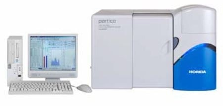
Figure 2
The LCSF compound is synthesized via a solid-state process. A coarse material is produced upon calcining the oxide mixture, which is then milled to a final particle size. A stable refractive index for these materials must be determined, as their values are not available in literature.
To achieve this, LA-950 software was used to observe the changes in the optical model on how well the measured intensities fit the calculated intensities, using Chi2 and R to test how appropriate the optical parameters used are. The first step was determining the real component as 2.0.
Next, a suitable imaginary component was selected using the Chi2 and R calculations. Figure 2 shows a plot of how the fit parameters vary as the imaginary part of the refractive index was changed from 0 to 1.1, resulting in a chosen value of 2-0.3i as the complex refractive index.
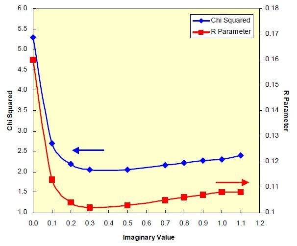
Figure 3
The LCSF powder was ball milled in water, using 1 mm YSZ beads for 11 hours. The particle size reduction with milling, as measured using the LA-950, is shown in Figure 4. The final median particle size was about 0.5 µm, with a clear narrowing of the particle size distribution with milling duration, which the analyzer was able to show very clearly, even when the changes in particle size were minute (Figure 5).
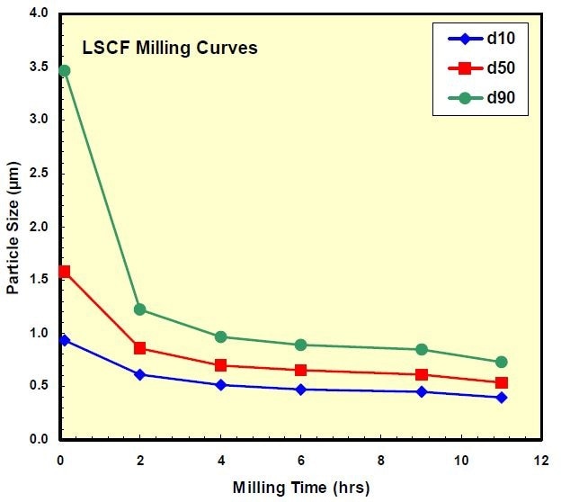
Figure 4
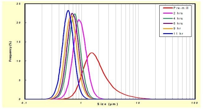
Figure 5
Porosity of electrodes is paramount in SOFC, and the information provided by the particle size analyzer can be used to control the porosity to achieve specified levels. The minimum achievable porosity for a specific distribution or combinations of distributions can be estimated using the particle packing calculations described by Dinger (Particle Calculations for Ceramists, 2001, D. R. Dinger Publishing, Clemson, SC).
The calculations require the volume fractions of the individual size classes as given by the cumulative percent finer than (CPFT) distribution provided by the LA-950 analysis. These calculated porosity values apply to an unfired structure and are significantly higher than those found after sintering.
The calculations show that a single narrow distribution will yield the most open structure, whereas a broader distribution will produce a more dense structure. Table 2 shows that most particle size distributions produced by milling give an open, unfired structure with approximately 30 vol% porosity.
If the goal was to minimize the porosity of the final part, as is needed for the electrolyte, it could be met by using a broad distribution. In the extreme case as shown in Figure 6, the porosity could become 11.3%. It can be brought down further by adding other finer distributions to the broad one. Calculations show that such a combination can bring down the minimum achievable porosity to around 8% (Figure 7).
Table 2
| Component |
Minimum Porosity (%) |
| Pre-Mill |
27.2 |
| 2 hrs |
31.9 |
| 4 hrs |
32.2 |
| 6 hrs |
32.1 |
| 9 hrs |
32.4 |
| 11 hrs |
32.5 |
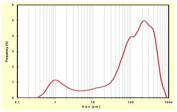
Figure 6
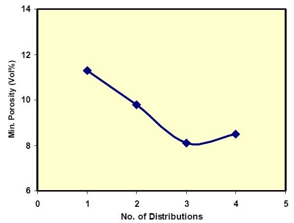
Figure 7
Conclusion
Particle size distribution is vital in any ceramic application. In SOFCs, PSD governs the final pore structure, which is important for the electrochemical performance of the cell. Having an accurate description of the PSD can allow engineers to tailor the final microstructure of materials.

This information has been sourced, reviewed and adapted from materials provided by HORIBA.
For more information on this source, please visit HORIBA.