| Throughout the world many reinforced concrete bridges are in a dilapidated state. There are many reasons for this, but one of the more common is cracking of the concrete leading to exposure of the steel reinforcement structure. When this is coupled with increasingly heavy traffic loads the state of the bridge rapidly deteriorates. However, the cost of replacing or repairing all the damaged bridges using conventional means, even in prosperous western European countries, is prohibitive and, if conventional approaches are taken, the possibility of the concrete structure’s deterioration over time remains. Alternative Technology to Reinforced Concrete Bridges In an attempt to solve these problems a European funded project was set up. Called Advanced Structural Systems for Tomorrow’s Infrastructure’ (ASSET), the project consisted of a European consortium led by Mouchel (UK) and included Fiberline Composites (Denmark), Skanska (Sweden), Oxfordshire County Council (UK), HIM (The Netherlands), IETCC (Spain) and Kungl Hogskolan (Sweden). The objectives of the project were to develop a competitively priced structure with distinct user benefits, such as durability, lightweight and a speedy and developed system of construction. This depended on the development of an optimised profile as a structural member capable of carrying various loads and made of glass/carbon fibres and thermosetting resin, manufactured by pultrusion. In turn this required the development of the pultrusion process for mass production of the profile and ways of connecting all the components of the bridge. The final part of the four year project was to design and test large-scale bridge deck structures, built using the technology developed, in real-life service conditions in the UK road network. Design Parameters for the Fibre Reinforced Plastic Bridge The depth, size and profile of the decking planks were the result of several considerations. At an early stage it was decided that the decking would span the main longitudinal beams - following the study of typical bridge decking applications, a length of two metres was determined as the most useful. With regards to the loads that the profile would have to carry, it was decided to apply British standards, as these were the most demanding, while depth and cross-sectional size was chosen as approximately 250mm x 500mm as these would ensure maximum compatibility with existing bridges and would ensure suitability for manufacture by pultrusion. Pultrusion as the Manufacturing Process Pultrusion was chosen because the process ensures stability of the dimensions, it is cost-effective with consistent quality and is a process that lends itself to mass production. The geometry for the individual ASSET planks that would make up the decking were determined by their functionality, efficiency, production friendliness, resistance and their cost of manufacture. According to Danish-based Fiberline, the partners who produced both the profiles and load carrying beams (figure 1), one of the biggest problems in manufacturing profiles of such a size (about 30kg per metre) is the very large pulling force required. However, development work carried out with a trial tool reduced the pulling force to the extent that modification of an existing line, rather than the building of a complete new line was all that was required. The final design of the profile came out at 300mm wide by 225mm deep and has the ability to be glued or bolted together, although during construction the bolted joint was found to be considerably more complicated than the bonded joint. The beams to carry the profiles were far more traditional in shape - four 240mm square sections were bonded together to provide rigid box section. | 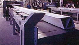
| | Figure 1. A pultruded deck section made from fibre reinforced plastics. | Testing of Fibre Reinforced Sections Before the profiles could be used they had to be thoroughly tested. Carried out at IETCC in Spain, the profiles were subjected to static flexure, static shear, fatigue, creep and impact testing. Small-scale coupon tests were carried out on the GRP composite material and the decking was analysed using 3D finite element model analysis. Additionally, static, fatigue and creep testes were carried out on single and multiple profiles over one and two spans, and in all cases the profiles matched their expected performance to within 5%, with only slight thickening of one of the diagonals required. Trialling the Fibre Reinforced Bridge Design All that was needed to complete the project was a client who wanted a bridge, and who was prepared to act as a trail-blazer for the technology. West Mill Bridge in Oxfordshire was built in the 1870s and carried a single lane of traffic over the river Cole. Oxfordshire County Council was a member of the ASSET consortium, so when the bridge was due for renewal it was an obvious candidate for the new technology. Owing to the dilapidated condition of the existing abutments and the need for increased carriageway width, it was decided that the existing abutments would be demolished and reconstructed in reinforced concrete - while this was taking place the deck was to be constructed on site for lifting into position once the abutments were completed. Construction of the New Bridge Once the existing bridge had been removed, sheet pile cofferdams were installed on either side of the river. Alongside the bridge, a fabrication area was constructed with temporary works erected to support the deck under a humidity-controlled tent. Here, the longitudinal beams were placed and the edge beams cast in concrete. ASSET profiles, prebonded into seven sections, were then placed on top, ready for bonding. Once glued into position, ‘L’ profiles were bonded to their sides to form the edges of the footpath and optical sensors and strain gauges installed at key locations to enable real-time, in-service monitoring to take place. With the completion of the abutments, a 200 tonne mobile crane was a positioned to lift the completed deck into position. When in place, final carriageway works were completed, including the reconnection of a gas main. The bridge deck surfacing comprised of polymer concrete topping, which was finished with a 6mm thick anti-skid, epoxy wearing surface supplied by HIM. | 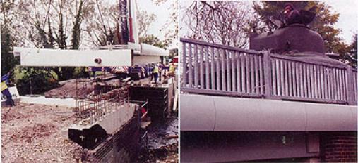
| | Figure 2. The fibre reinforced polymer deck section being lifted into position (left) and being tested under the load of a Sherman tank (right). | Summary Overall, the client, construction team, pultruder and project management team were all pleased with the final result. The ASSET profile construction system proved to be faster and cheaper to construct than comparable concrete or steel structures and the bridge should be more durable, as well as being almost maintenance-free. Already there are plans for the wider use of the ASSET profile in jetties, helipads, industrial plants, car parks and further bridges. The plastic bridge in Oxfordshire looks set to be the start of a construction revolution. |