Coherence Scanning interferometers are ideal for measuring the surface topography of fine structures. These versatile instruments are suitable for use in production and development environments, as well as in laboratories and research settings.
The underlying measurement technology accommodates almost all types of materials. It is non-contact and able to provide 3D surface maps and line profiles with height resolutions in the nanometer range.
The TopMap family of systems include large-area measurements as well as detailed investigations with high lateral resolution; for example, when working with optical components, the surface characterization of wafers, or tribology applications.
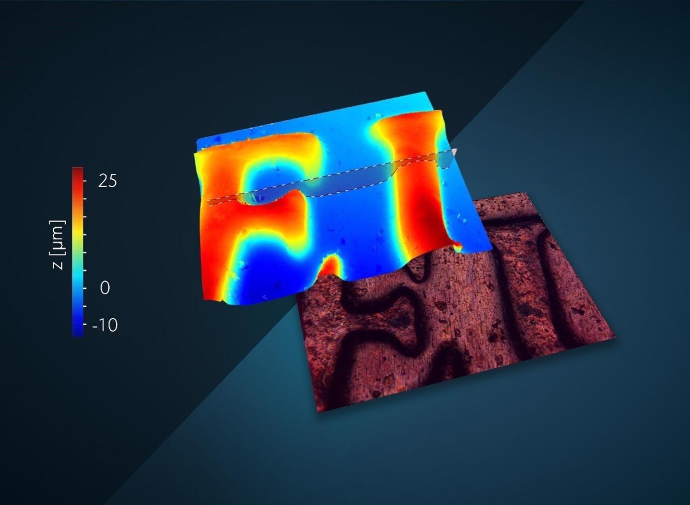
Image Credit: Polytec
The unambiguous height determination technology uses interference effects that occurs as light reflected from an object under investigation is superimposed with that from a reference signal.
A beam splitter is used to direct a collimated (parallel or straightened) light source into measurement and reference beams.
The measurement beam then strikes the object under investigation, while the reference beam strikes a mirror. Light reflected from both the object and the mirror will recombine at the beam splitter before being focused onto a camera.
Every pixel in the camera array acts as a virtual probe being energized only when interference occurs. This temporal condition in sync with the readout of the focusing stage will determine the representation of height position of all pixels with respect to each other.
Should high lateral resolution be required, it may be more appropriate to use a microscope-based system, in which the optical configuration and reference arm are integrated into the lens.
TopMap Micro.View/Micro.View+: High Resolution Across Entire Measurement Range
Polytec has offered the TopMap series of white-light interferometers for several years.
These systems have proven themselves in a number of applications; for example, flatness measurements on sealing surfaces, detection of warpage, determining the curvature of diaphragms, or the detection of form deviations on pumps and high-pressure components.
Demand for measurements of structural details such as roughness has significantly increased. There has also been an increase in the use of motorized accessories, including encoded turret and positioning stages such as tip/tilt stages.
These increasing demands and industry requirements have led to the TopMap series being extended to include microscope-based models, the Micro.View and Micro.View+. Both offer considerably higher number of data points in the x and y direction, while utilizing the Polytec continuous scanning technology to perform measurements across the entire vertical measurement range of 100 mm, rather than just a few micrometers.
This approach allows substantially more detailed measurements to be acquired, for example, the detection of microstructures on wafer surfaces, analysis of microstructures found in printing processes, or determining surface roughness in optical components.
The object’s color information may also be incorporated in addition to the height measurement, helping differentiate surface anomalies when topography is just not enough, simplifying defect detection while enhancing reporting capabilities.
Additionally, the Micro.View and Micro.View+ employed in harsh production environments may be enabled with ECT (environmental compensation technology) to compensate for environmental disturbances.
Two Models and a Range of Possibilities
The compact, tabletop version - TopMap Micro.View – has been designed to offer an entry-level solution that can be utilized quickly and easily as a standalone instrument anywhere, for example, in research institutes or smaller test laboratories.
The 100mm Z stage is motorized while the objective turret and XY stages may be configured as manual or motorized.
The larger format and modular TopMap Micro.View+ offers flexibility and performance advancements for a diverse set of applications. This instrument offers motorized x, y, z axes with a 200 × 200 × 100 mm3 travel range. An optional motorized tip/tilt stage is also available.
When equipped with all motorized translation stages, measurements can be run automatically according to specific ‘recipes.’
Given the modular gantry design, using riser blocks, the sensor head may be elevated to accommodate tall parts, and additionally, the sensor head can also be integrated directly into the production line if required.
Both the Micro.View and Micro.View+ are available with autofocus and automatic focus tracker functions to ensure that the surface of interest remains in view. The focus tracker operates in a similar fashion to facial recognition technology; the system continually compensates for part motion and the surface remains in focus.
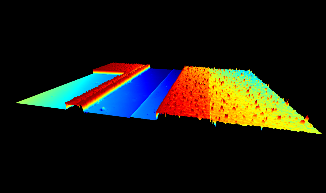
Etched Structures on Si Wafer
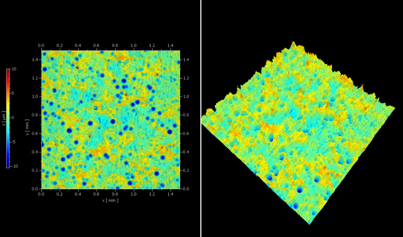
Texture of Print Media
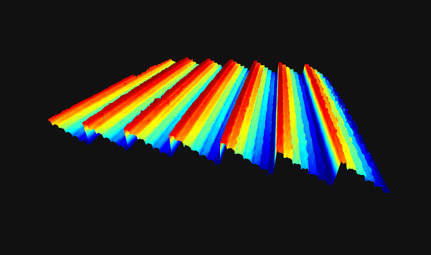
Diffractive Optic Section
New microscope systems with high lateral resolution across the entire measurement range up to 100 mm. Image Credit: Polytec
A Single Source for Hardware and Software
The TMS software has been specifically developed for use with Polytec topography measurement systems. In addition to acquiring and analyzing measured data for a complete turn-key solution, also included is a range of available export options for processing in any 3rd party evaluation software package.
The TMS software offers various options for rapidly evaluating measurement results in accordance with ISO standards.
‘Measurement recipes’ are available, which make routine tasks simpler. These recipes provide user-definable settings for data acquisition such as camera parameters, measurement position and illumination settings, as well as pre-set evaluation parameters including post-processing steps, export or visualization options.
This function effectively turns complex surface analyses and special measurement functions into simple one-click solutions, saving time in the production environment and minimizing operator influence.
Feasibility studies and project support is available to help users in optimizing and selecting the appropriate system and accessories.
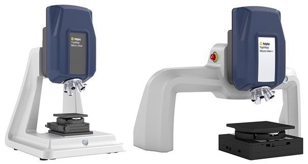
TopMap Micro.View (l) and Micro.View+ (r)
Detailed measurements with high lateral resolution, e.g. to detect microstructures on wafer surfaces (a), to analyze droplet distribution in printing processes (b) or to determine surface roughness of optical components (c). Image Credit: Polytec

This information has been sourced, reviewed and adapted from materials provided by Polytec.
For more information on this source, please visit Polytec