Introduction The application of thin hard coating layers on HSS tools using PVD technique has created a revolution in metal cutting and forming. It is widely understood that the coatings on the rake face of the turning tool change frictional interactions between chip and tool, particularly in continuous chip formation resulting in shortening chip/tool contact length and changing temperature distribution on it. Life of the cutting tool therefore increases by ten times [1, 2]. According to Loffler [3], temperature or cutting speed is the major factor affecting wear mechanisms. At slow cutting speeds, adhesion and abrasion are the main wear mechanisms. Abrasion and chemical wear are essential at high cutting speeds, especially in continuous chip formation. Banh et al. [4] confirmed the role of coating layer in reducing temperature and heat affected zone (HAZ) on rake face of PVD-TiN High Speed Steel (HSS) turning tools used to machine medium carbon steels to be the principal reason for longer tool life of the cutting tools. Soderberg et al. [5] carried out a study of wear mechanisms for milling tools using to machine medium carbon steels. They found that a combination of high cutting speed and low feed rates are detrimental for tool life. This is consistent with study of tool life equation for TiN coated endmills in which not only high cutting speeds but also high feed rates are preferable for longer tool life [2]. Five wear mechanisms of the milling tools were observed including edge chipping, plastic deformation of the edge, wear by shear fracture, continuous wear and wear by superficial plastic flow. Both flank and rake face wear were evident in the study [5, 6]. In a related topic, Medicus et al. [3] used both uncoated and TiN, TiCN, TiAlN coated cemented tungsten carbide endmills to machine aluminum bronze at high cutting speeds and feed rates. Dulling cutting edge and the formation of a leading edge notch were the main types of wear. Ismail et al. [7] built a model for surface formation by endmill in relation with tool wear on flank face. The purpose of this research is to find the role of the coating layer in the increase in coated endmill's life. Furthermore, in this work, the effect of high temperature (≥600°) on the failure of the cutting tool at high cutting speeds will be addressed. Experimental Procedure The experiments carried out in this investigation involved machining slots on a conventional vertical 6P12 milling machine made in Russia. A Kistler dynamometer, type 9257BA was used to measure components of cutting forces on the plane perpendicular to the axis of the uncoated and coated HSS endmills. A block caliper with the accuracy of 2 μm was used to measure the reduction of tool diameter (ΔD) due to wear. The cutting tools, workpiece and machining conditions are detailed below: Commercial endmills diameter 10 mm with two flutes were used. The tools were PVD TiN or TiCN coated to 3 μm thick. Uncoated endmills were used as a reference. The hardness of the flute part was 62-65 Rockwell C (HRC). It was evident in previous studies [3, 8] that the TiN coating layer on the rake face plays a much more important role in tool's performance compared with the coating layer on flank face. The coating layer on the main flank face of the coated endmills in this study was ground off to prove the above finding in case of complex tools. Geometry parameters of the tools are shown in Table 1. Table 1. Geometry parameters of the tools. The workpiece was 30 mm diameter-spindles hardened and tempered to the hardness of 24-28 HRC. The chemical compositions of the tools and workpieces that were obtained by spectrographic analysis are shown in Table 2. Cutting conditions were selected in ranges: cutting speeds: 18.85 m/min to 31.25 m/min; feed rates: f = 63 mm/min to 100 mm/min; depth of cut: d = 4 mm = const for uncoated tools and cutting speeds: 31.25 m/min to 50.26m/min; feed rates: f = 100 mm/min to 800 mm/min, depth of cut: d = 4 mm = const for coated tools. All are detailed in reference [2]. Tool wear is estimated by the reduction of endmill's diameter (ΔD). The coated tool was about to fail when ΔD reached approximately 60 µm. Table 2. Chemical compositions of the tools and workpieces | | | M41 | 1.0945 | 0.3284 | 0.2657 | 0.0035 | 00123 | 0.1025 | 3.7448 | 4.4797 | 0.1331 | 1.4305 | 0.0049 | 0.8128 | 4.9797 | | 45 steel | 0.4752 | 0.5188 | 0.2787 | 0.0055 | 0.0205 | 0.0655 | 0.0619 | 0.002 | 0.105 | 0.0022 | 0.0009 | 0.0025 | 0.0088 | Dry cutting was applied in this study. The tools after machined were cut and examined on Scanning Electron Microscope (SEM) type JM6400. Results and Discussion Figure 1 shows an example of measured components of cutting forces when uncoated and TiN coated endmills were used under cutting conditions: v = 31.25 m/min, f = 100 mm/min, d = 4 mm. In the case of an uncoated tool, cutting force components were Fx = 0.48 KN and Fy = 0.276 KN. However, when TiN coated tools were used, the two cutting measured components were Fx = 0.424 KN and Py = 0.163 KN. The feed force (Fx) reduced by 12% and Fy reduced by 40%. Moreover, vibration of Fy reduced considerably when coated tools were used. The effect of TiN on reduction of cutting forces is therefore evident. | 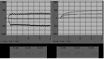
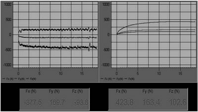
| | Figure 1. (a) Graphic outputs of the Fx and Fy cutting forces of an uncoated M41 endmill using cutting condition (v = 31.25 m/min, f = 100 mm/min, d = 4mm) to machine 45 hardened steel. (b) Graphic outputs of the Fx and Fy cutting forces of a PVD-TiN coated endmill using cutting condition (v = 31.25 m/min, f = 100 mm/min, d = 4 mm) to machine 45 hardened steel. | Tool life of the uncoated endmills using cutting conditions (v = 31.25 m/min, f = 100 mm/min, d = 4 mm) was only 0.5 min. The use of PVD-TiN coated tools increased their lives about 10 fold. Moreover, at optimal cutting conditions (v = 37 m/min, f = 160 mm/min, d = 4 mm) the life of TiN coated tools was about 8.95 min. When a PVD-TiCN coated endmill was used under the same cutting conditions as TiN coated one, the cutting forces were considerably reduced as evidence in Figure 2(b) compared with those in Figure 2(a) (Fx by approximately 30% and Fy by approximately 24%). Moreover, a reduction of cutting forces vibration was also observed. TiCN is therefore superior to TiN in the intermittent cutting. This finding is consistent with publications of other authors. | 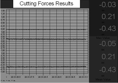
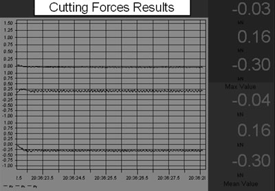
| | Figure 2. (a) Graphic outputs of the Fx and Fy cutting forces of a PVD-TiN coated M41 endmill using cutting condition v = 39.26 m/min, f = 250 mm/min, d = 4mm to machine 45 hardened steel. (b) Graphic outputs of the Fx and Fy cutting forces of a PVD-TiCN coated M41 endmill using cutting condition of v = 39.26 m/min, f = 250 mm/min, d = 4 mm to machine 45 hardened steel. | Lives of the coated endmills in this study were recorded and then analyzed with the application of a regression program in Matlab. A tool life equation in the second-order logarithmic form is derived as follows:
lnT=-64.7857 + 0.35653lnf + 36.187lnV + 3.4084(lnf)(lnV) - 1.263(lnf)2 - 7.3196(lnV)2 A connection between longer lives of the TiN coated M41 endmills and wear mechanisms was investigated. SEM of uncoated M41 endmills after 0.3 min of cutting as shown in Figure 3(a) revealed wear of uncoated endmills took place on both corner and relief flank face of the leading edge. The width of wear land on the relief flank face and corner wear is slightly different. Further SEM examinations of the corner wear detected evidence of serious adhesive wear with material transfer as shown in Figure 3(b). Energy Dispersive X-Ray (EDX) analysis of the material transfer revealed workpiece material with Fe and little Mn, Cr, Al and Si as shown in Figure 6(a). | 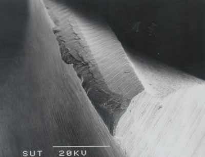
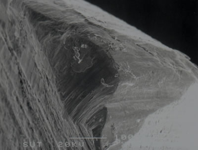
| | Figure 3. (a) SEM micrograph showing corner wear and relief flank wear of the leading edge of an uncoated M41 endmill (v = 18.85 m/min, f = 100 mm/min, d = 4 mm). (b) Higher magnification of the corner wear of the uncoated M41 endmill showing intensive adhesion wear. | The wear pattern of PVD- TiCN and TiN coated endmills was completely different from uncoated tools. This is evident in Figure 4(a) compared with Figure 3(a). The corner wear has a triangle shape and the width of relief flank wear is about a fourth of the corner wear. EDX analysis of the corner wear on Figure 6(b) shows only little material transfer. In other tool samples, flank wear was also observed along with the relief flank wear. | 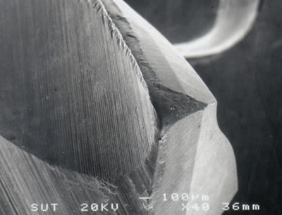
| | Figure 4. (a) SEM micrograph showing corner wear and relief flank wear of the leading edge of an TiCN coated M41 endmill (v = 39.26 m/min, f = 250 mm/min, d = 4 mm). (b) Higher magnification of corner wear of the coated M41 endmill showing negligible material transfer. | Figure 5(a) shows wear pattern on the relief flank face of the leading edge of a TiCN coated endmill after 2 min cutting. The coating layer in the vicinity of the cutting edge was worn out, but there is no evident of gross work material transfer on this region. EDX analysis of the region further from the cutting edge detected Ti and little Fe showing work material transfer on the coating. However, elements in inclusions in the steel were not found in the material transfer as in study [4]. | 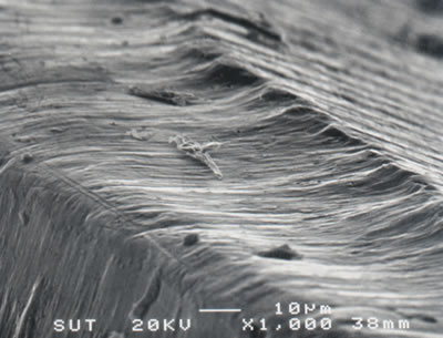
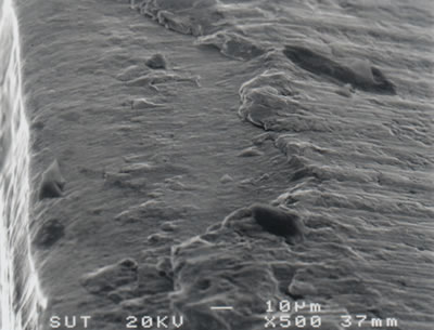
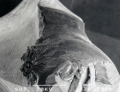
| | Figure 5. (a) SEM micrograph showing relief flank wear of the leading edge of a TiCN coated M41 endmill (v = 39.26 m/min, f = 250 mm/min, d = 4 mm). (b) SEM micrograph showing relief flank wear of the leading edge of a TiN coated M41 endmill (v = 39.26 m/min, f = 250 mm/min, d = 4 mm). | Figure 5(b) shows wear on the relief flank face of the leading edge of a TiN coated endmill after 5 min cutting. Abrasive wear is clearly evident on this region. The pattern of wear land is quite similar to the crater wear on the rake face of the turning tool. Not much work material transfer is observed in this area. EDX analysis detected only tool material with Fe, Cr, V, Mo, W and Al as shown in Figure 6(b). | 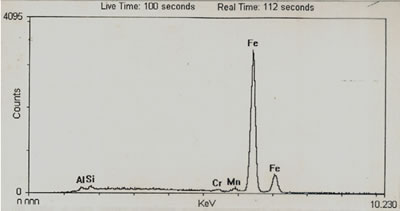
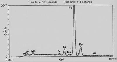
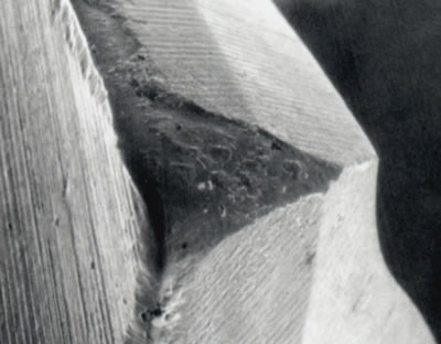
| | Figure 6. (a) EDX analysis of the material transfer in Figure 3(a) showing chemical composition of work material with Fe and little Mn, Cr, Al and Si. (b) EDX analysis of wear land in Figure 4(a) and 5(b) showing chemical compositions of tool material. | Rake face wear was then evident at the corner making rake angle negative as shown in Figure 7(a) and 7(b). Consequently, high temperature (≥600°C) might develop in the vicinity of the cutting edge causing the failure of the cutting tools [1, 9]. The starting point of the controlled temperature failure was observed either the corner or at a place on the leading edge where the tool is in contacts with the workpiece’s surface. | 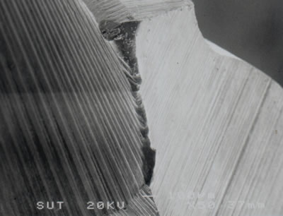
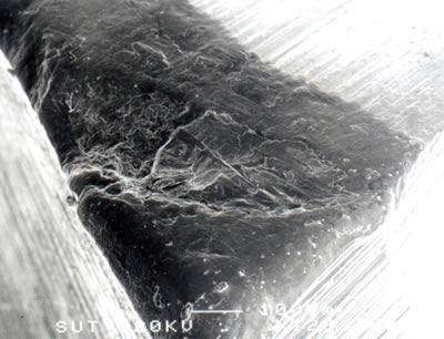
| | Figure 7. (a) SEM micrograph showing wear at corner on the rake face of a TiN coated M41 endmill (v = 39.26 m/min, f = 250 mm/min, d = 4 mm after 5 min of cutting). (b) SEM micrograph showing wear at corner on the rake face of a TiN coated M41 endmill (v = 50.26 m/min, f = 250 mm/min, d = 4 mm after 7 min of cutting). | It is interesting to note that when high feed rates were applied, high cutting forces were recorded and were a cause of breakage of the corner and cutting edge as shown in Figure 8(a). At the highest cutting speed in the study (50.26 m/min), TiN coated tools failed immediately by another mechanism, gross plastic deformation due to high temperature after the width of wear land reached a critical value as shown in Figure 8(b). Red color was observed during experiment before the tool was stopped cutting. Just before the wear land’s width reached the critical value (ΔDmax ≈ 60µm) adhesion was observed on the rake face of the corner and the leading cutting edge. | 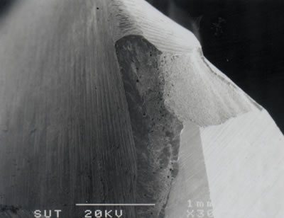
| | Figure 8. (a) SEM micrograph showing breakage of corner and cutting edge of a TiN coated M41 endmill (v = 39.26 m/min, f = 630 mm/min, d = 4 mm). (b) SEM micrograph showing gross plastic deformation of corner region of a TiN coated M41 endmill as a result of high temperature (v = 50.26 m/min, f = 250 mm/min, d = 4 mm). | Based on cutting force measurements, tool life and observation of wear of the cutting tools in the SEM, it is clear that different wear mechanisms took place on uncoated and coated endmills. In case of uncoated endmills cutting at slow and normal cutting speeds, adhesion was a major wear mechanism that took place at the corner and flank face of both cutting edge and leading cutting edge. Direct metal – metal contact between work and tool materials is reason for material transfer at interfaces resulting in high cutting forces and high amplitudes of their vibrations. The uncoated tools therefore were not able to machine at high cutting speeds and failed soon by breakage of the tools after only 0.5 min of cutting with cutting condition (v = 31.25 m/min, f = 100 mm/min, d = 4 mm). In case of coated tools cutting at normal and high cutting speeds, tool life could increase to approximately 9 min at the optimal cutting condition computed from the tool life equation. The coating layer at rear flank wear reduces development of the wear land due to its low adhesion with work material in that region. High hardness, low adhesion and friction with work material and chemical inertness of the coating layer contribute to a reduction of wear rates and an increase in tool life. Abrasive wear is evident in Figure 5(b) and the high capacity of the coatings resist this type of wear would result in a long life of the tool. Adhesion is not clearly observed on relief flank wear. This is consistent with the dependence of wear mechanisms on cutting speed [3]. Higher cutting speeds are favorable for abrasive wear and the existence of the coating at the wear land boundaries prevent it from adhesion. Hard particles in forms of oxides and carbides in work material and carbide particles in tool material are believed to be the source of abrasive wear particles. According to Trent and Wright [9], at high cutting speed the highest temperature point is located at a distance from the cutting edge on the flak face. It is reasonable to conclude that temperature can contribute to deepened effect at rear relief flank wear. It is widely accepted that high cutting speeds result in low cutting forces and high temperature at the interfaces between work and tool materials [9]. In this study, feed rates have major effects on increases of cutting forces. The higher feed rates are applied the higher cutting forces are measured. High cutting forces cause breakage of the corner and cutting edge (mechanical failure). In contrast, high cutting speeds and normal feed rates result in failure of the cutting tool due to high temperature as shown in Figure 8(b). When the width of wear land develops to a critical value, temperature of more or less 600°C (at which HSS is about to be softened dramatically) generated and developed into tool materials at the interface between cut surface and relief flank face or the tool corner resulting in gross plastic deformation. The hard coating layer on the boundaries of the relief flank face wear retards the development of the width of wear land and eliminates considerably material transfer leading to possibility of using higher cutting speeds. The use of high cutting speeds is a factor to reduce cutting forces, but generates high temperature. Therefore, the tool could fail by mechanisms controlled by temperature. Other wear mechanisms as mentioned in the introduction part could contribute to wear of the cutting tools in this study. However, the authors paid attention on only major wear mechanisms causing the failure of the cutting tools. Conclusions Adhesive wear on corner and flank faces is the main wear mechanism when using uncoated M41-HSS endmills to machine slots on 1045 hardened workpieces at cutting speeds less than 20 m/min. Hard coating layer changes frictional contact conditions between work and tool materials resulting in application of much higher cutting conditions. The coating reduces considerably cutting forces, gross work material transfer, and abrasive wear even when the coating was worn out at the vicinity of the cutting edge. The pattern of wear land at the corner wear of the coated tools is completely different of the uncoated ones. Abrasive wear was evident on flank faces. Longer tool life is achieved with the coated tools. Gross plastic deformation, the failure mechanism controlled by high temperature is observed at high cutting speeds and feed rates. Acknowledgements Dr. Q.T. Phan would like to acknowledge the financial support of the Vietnamese Ministry of Education and Training and the technical support of Suranaree University of Technology – Thailand during the period the work was implemented. The authors wish to express special thanks to Song Cong Diesel Company, especially Mr. Nguyen Van Khoi, Director of the company for his invaluable helps in carrying out our experiments. References 1. K. Holmberg and A Matthews, "Coating Tribology - Properties, Techniques and Applications in Surface Engineering", Elsevier, New York, (1994). 2. Q.T. Phan, D.H. Nguyen, D.B. Nguyen and C.N.Tran, “Tool Life Equation for TiN Coated Endmills”, the International Conference in Commemoration for the 50th Anniversary of Chung Nam National University, May 22–24 (2002) 203-208. 3. F. H. W. Loffler, "Systematic Approach to Improve the Performance of PVD Coatings for Tools Applications", Surface and Coatings Technology, 68/69 (1994) 729-740. 4. T.L. Banh, Q.T. Phan and D.H. Nguyen, “Wear of PVD Coated HSS Tools Using to Machine Medium Steel”, The first Korea-Vietnam International Joint Symposium on Advanced Materials, Chung Nam National University, November 4– 5 (2002) 64-172. 5. S. Soderberg, S. Hogmark, H. Haag and H. Wisell, "Wear Resistance of High Speed Steel Milling Tools", Metal Technology, 10 (1983) 471-481. 6. K. M. Medicus, M. A. Davies, B. S. Dutterer, C. J. Evans and R.S. Fielder, "Tool Wear and Surface Finish in High Speed Milling of Aluminun Bronze", Machining Science and Technology, 5 (2001) 255-268. 7. F. Ismail, M. A. Elbestawi, R. Du and K. Urbasik, "Generation of Milled Surfaces Including Tool Dynamics and Wear", Journal of Engineering for Industry, 115 (1993) 245-252. 8. Q.T. Phan, “An Examination of Tribological Contact between Chip and Rake Face of PVD-TiN coated HSS Tools”, Master Thesis, Swinburne University of Technology- Australia, (1996). 9. E. M. Trent and P. K. Wright, "Metal Cutting", Butterworth-Heinemann, USA, (2000). Contact Details |