Sponsored by AdmesyApr 26 2018
Incident light on a transparent surface may either be reflected, transmitted or absorbed according to the laws of optics.

Image Credits: Gumpanat/shutterstock.com
Whenever there is a boundary between two different surfaces, light is refracted because there is a change in the speed of light when it crosses from one material to another. The direction in which it bends, i.e., towards or away from the line of normal incidence, depends on whether the speed decreases or increases upon crossing the boundary. Materials with the highest refractive index slow down light waves the most, and hence have the highest bending.
Transparent materials allow light to pass through without any major absorption of the incident light. However, translucent materials do not transmit most of the light that passes through them as they have structures that cause light to scatter.
Translucent Materials
Snell’s law, which states that the ratio of the sines of the angles of incidence and refraction of light remains constant when it passes through a boundary, is used to determine how light will behave when it passes from one medium to another. Translucent materials allow light to pass through but do not necessarily follow Snell’s law.
In these materials, photons may be scattered at any of the interfaces where there is a change in the refractive index, and there may be internal reflection, such that a part of the light incident is absorbed, transmitted, and reflected.
Transmission can be straight through, diffused, or something between the two. When measuring the transmission of translucent materials, this difference between diffuse and non-diffuse materials causes additional challenges.
Transmission Measurement
Transmission measurements usually consist of two steps. First, establishing a spectral baseline by measuring a standard light source without the material, and then, measuring with the sample. The difference between the measurements gives the transmission characteristics of the material.
A standard light source as a reference, such as any stabilized source like an LED or halogen light source capable of emitting the entire wavelength range of interest for the sample being tested, and a detector are required for the measurements.
If light is not emitted at certain wavelengths, none is transmitted, so no properties can be ascertained from the measured data. Another important point is that the overall spectral sensor response along with the spectral power distribution of the light source should have a suitable signal-to-noise ratio.
If the angle of the transmitted beam through a translucent material can be calculated from the incident angle and Snell’s law, the transmission measurement setup for translucent materials is simple. However, in some materials and applications scattering can be important, particularly in diffusing filters.
Translucence Requirements
When considering the measurement geometry it is important to take into account that translucent materials (diffuse and non-diffuse) have very specific transmission properties. Various options, including using lenses/collimators for emitting and receiving light, cosine correctors, integrating spheres, and combinations of these optics are possible.
If the translucent material is highly diffusing, an integrating sphere may be required to collect all the light. But, this may decrease the signal-to-noise ratio because of low light output, adversely affecting measurements.
Light Sources and Spectrometers
A light source and detector that match the desired spectral region of the material of interest are important for obtaining good spectral data. A range of Steropes light sources are available from Admesy including white and colored LED light sources and halogen with optional blue enhancement filter. These light sources cover a broad spectrum from visible to near infrared and are suitable for a majority of applications.
An important part of obtaining useful transmission measurement data is the spectrometer configuration. Along with being sensitive over the wavelength range of interest, suitable optical resolution for the application is also necessary.
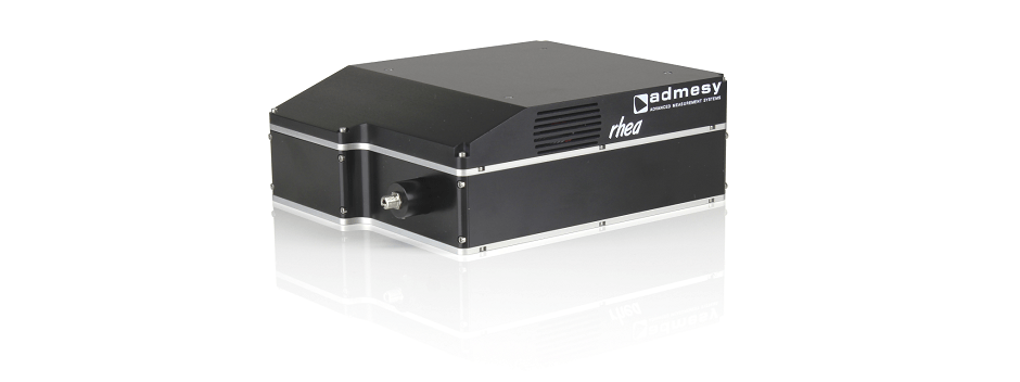
The Rhea series of spectrometers from Admesy. Image Credit: Admesy
The Rhea series of spectrometers from Admesy are fully customizable and sensitive between 200 and 1100 nm because of a cooled Hamamatsu CCD detector. The features of the Rhea are:
- Can be used for slit sizes (which control the amount of light entering the optical bench) from 10–100 µm. A smaller slit size reduces the FWHM and increases the resolution
- Gratings sizes range from 200 to 1800 grooves/mm. A spectrometer grating disperses light into individual wavelengths and dispersion is determined by the number of grooves, given by grooves/mm. The higher the number of grooves, the higher the dispersion.
- Customizable gratings can be used on the Rhea, allowing for the analysis of a wide or specific wavelength range. Although higher number of grooves increases the dispersion, this also limits the range of wavelengths that can be resolved because the detector has a fixed width.
- The Rhea includes a filter wheel with a shutter function and 5 ND filters (OD0 as standard position, OD1, OD2, OD3 and OD4). This allows the spectrometer to have a large dynamic range and measure optical densities above 4.0.
- The start and end wavelength can be determined to fit the specific transmission measurement application using the grating choice and alignment.
A fully customizable setup and wide dynamic range allowing for transmission measurements over 200–1100 nm makes the Rhea an ideal spectrometer for optical spectral measurements in translucent materials. The number of gratings in the instrument is being increased, which will increase the number of configurations of the Rhea, expanding its usefulness.
 Download the Brochure for More Information
References
- Fox, M., 2002, Optical Properties of Solids. Oxford University Press.
- Application note, Transmission Measurement, Rhea and Steropes, Admesy, 2017
- Yamashita, I.; et al., 2008, Transparent Ceramics, J. Am. Ceram. Soc. 91 (3): 813.
- Singh, S., 2009, Fundamentals of Optical Engineering, Discovery Publishing House.

This information has been sourced, reviewed and adapted from materials provided by Admesy.
For more information on this source, please visit Admesy.