The application of in situ hybridization (ISH) has advanced from generalized, short-term isotopic methods, to long-term, highly specialized, multicolor Fluorescent-ISH probe assays (FISH).
Developments in filter technology, data handling, optics, cameras, and microscopes through software have allowed affordable FISH systems to be achievable for most researchers.
The application of mFISH (multiplex-FISH), along with the advancements in digital imaging microscopy, has strongly improved the capabilities for the analysis of multiple nucleic acid sequences in chromosomes and genes, and non-isotopic identification1.
Filters and Fluorescent Imaging
In an upright microscope, the fluorescence illuminator follows the epifluorescent path (overhead illumination) to the specimen.
The filter blocks are located in the pathway, which consists of the excitation filters, dichroic mirror, and emission. These work to significantly increase the brightness and contrast of the imaged specimens, even when multiple fluorochromes are being used.
Figure 1 demonstrates the standard configuration of the fluorescence illuminator on an upright microscope.
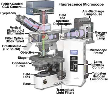
Figure 1.
The primary components in the episcopic (reflected illumination) pathway consist of the light source (a Mercury arc lamp in this example), a series of lenses that work to focus the light, and compensate for optical deviations as the beam moves in the direction of the filters.
Diaphragms are also included, which ensure balanced and effective illumination of the specimen, and the filter turret, which houses the filter sets.
The diagram schematically shows how the broadband excitation light from the source of light is precisely filtered to exclusively transmit the green component by utilizing the excitation filter in the turret. This is reflected in turn to the specimen by the dichromatic mirror.
The red fluorescence emission is transmitted back through the mirror via the objective lens and is filtered again by the emission filter before observation by eye or a camera.
Figure 2 shows an exploded image of the filter cube. The excitation filter is shown in yellow, and the emission filter is detailed in red to exhibit the standard band-pass Texas Red filter set.
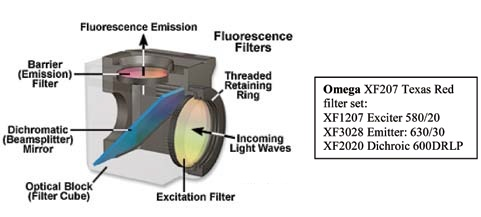
Figure 2.
Filter Descriptions
There are several ways of describing band-pass filters. The most widespread is the Center Wavelength (CWL) and Full Width Half Maximum (FWHM) nomenclature. Alternatively, they are known by nominal cut-on and cut-off wavelengths.
In the former, the exciter in Figure 2 is portrayed as a 580/20, or a filter with a nominal CWL of 580 nm and a FWHM of 20 nm. The half maximum value is taken at the value of transmission, where the filter has achieved 50% of its maximum value (Figure 3, Left).
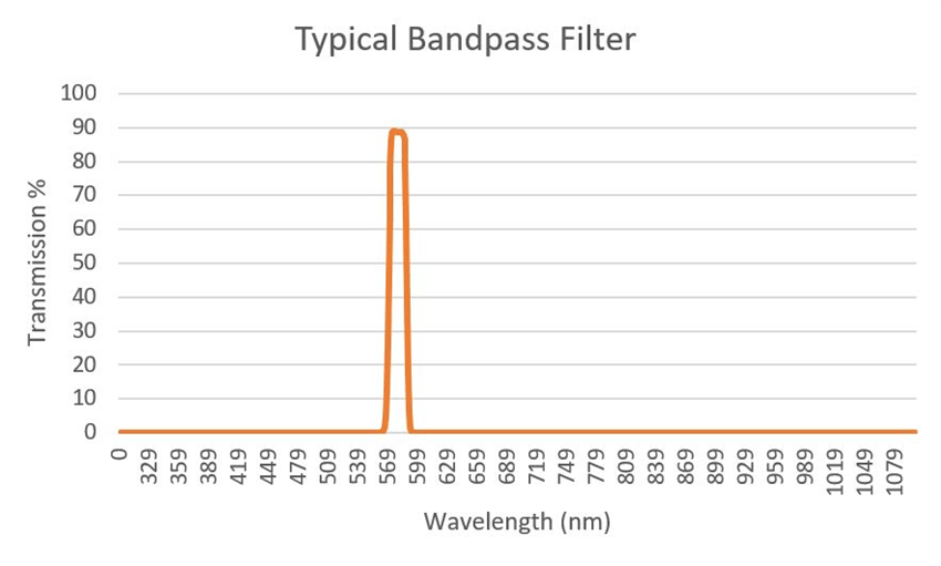
Figure 3.
In the latter scheme, the filter can be described as having a cut-off of 590 nm and a cut-on of 570nm, while the CWL is not detailed.
The cut-on describes the switch from filter attenuation to transmission along an axis of emerging wavelengths. The cut-off describes the switch back to attenuation after transmission. Each value identifies the 50% point of total transmission.
Cut-off and cut-on values are also used to account for two filters types known as long pass (or high pass) filters (presented in Figure 4) and short pass (or low pass) filters (presented in Figure 5).
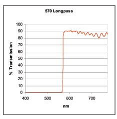
Figure 4.
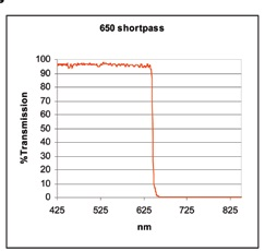
Figure 5.
A long pass filter is created to reflect and/or absorb light in a specific spectral region. It changes into transmission at the cut-on value (in this example 570 nm) and light that is greater than this value is transmitted along a broad wavelength range.
In short pass filters, the opposite is true; the wavelengths of light that are longer than the cut-off value at a given distance are blocked by these filters which transmit shorter wavelengths.
It is critical to note that these reflection and transmission regions are not endless, but are limited by the coating chemicals, the physical characteristics of light, and the features of the coating design.
In order to minimize the spectral bleedthrough of very closely spaced fluors in multicolor labeling schemes, specialized narrow band filter sets are needed.
Specialized Filters for FISH and mFISH
When imaging multiple fluorescent probes, special steps must be taken when organizing the filter blocks in the microscope turret. One method is the use of individual filter cubes for each probe in the specimen.
This is an effective technique for 6 color viewing (in most upright research microscopes, six is the average number of filter positions) as successful spectral isolation of the different probe species can be achieved through careful design of the filter.
This arrangement also reduces the chance of bleaching the probes because only one fluorescent species is illuminated at once.
A possible disadvantage of this scheme is a shift in image registration due to small filter misalignments. Slight deviation in the beam is an effect of this shift but can be observed when switching between several different filter cubes.
The dichroic mirror and the emission filter are the imaging elements of the filter cube and are the two components which can produce this effect.
An alternative method is to utilize distinct multiband dichroic mirrors and emission filters and to reject the exciter filters either in an external slider or a filter wheel.
The rejection will reduce mechanical vibrations and uphold the image registration, but the trade-offs are reduced dynamic range and sensitivity due to the color CCD camera required, limitations on the amount of different probes that can be separated, and a decreased fluorescent brightness.
Standard filter cubes are usually provided with fluorescent microscopes for the widespread Texas Red, FITC, TRITC, and DAPI stain fluors. Standard filter sets normally use wideband emission and excitation filters the most (sometimes long pass emission filters are used) in order to produce strong brightness.
When applying FISH, these regular sets can function successfully for 2, 3, and 4 color labeling, but spectral bleedthrough can easily become an issue. FITC is moderately visualized through the Cy3 filter for example, and Cy3.5 can be viewed via the Cy5 filter2.
Figure 6 demonstrates five separately-labeled chromosome pairs; the arrows in the top, middle, and bottom left images show the crosstalk in the middle of the channels. A pseudo-colored and overlaid image of the sequence is presented in the bottom right panel.
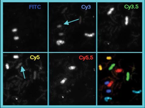
Figure 6.
Specialized narrow band filter sets are needed to prevent spectral bleedthrough of the fluors in multicolor labeling sequences that have little space to separate components.
Exciter filters of 10 to 20 nm and emission filters of 20 to 40 nm provide the required specificity to achieve the degree of sensitivity and spectral resolution required in mFISH.
Figure 7 shows a regular wide band FITC filter set overlaid on the emission and excitation peaks of FITC and Cy3.
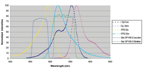
Figure 7. Image Credit: Omega Optical, Inc.
Although the filters are arranged to cover a considerable region under the absorption and emission curves, there is a strong overlap with both the excitation and emission curves of Cy3, resulting in the FITC channel to be contaminated by Cy3.
Figure 8 presents a solution to this. The excitation and emission bands have been constricted to increase the spectral resolution of FITC from Cy3, especially in the emission band. A reduction in the region under the emission curve of the Cy3 dye of approximately 4-fold is achieved by limiting the red edge of the emission filter.
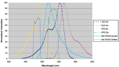
Figure 8.
Narrow band, steep-edged filters being incorporated in the design system broadens the spectral window for including multiple fluorescent probes without the cost of applying emission bleed between fluors.
This system can be seen in Figure 9, which details three fluors that have been effectively separated within a spectral window of below 300 nm. A fourth dye, such as Cy 3.5, could be incorporated in this process in the 570 to 620 nm region but is not included here to reduce congestion.
It is necessary to offer a specific range of products that work together to make optimal use of the bandwidth available for each mFISH fluor due to the demands placed on the filters used for mFISH.
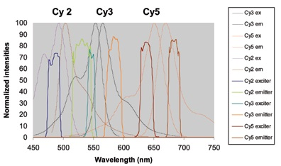
Figure 9.
Table 1 shows the Omega Optical range of filter sets for the most frequently utilized fluors in mFISH, along with providing the excitation and emission filter bandwidths.
Each of these are single fluor sets excluding XF231 and 232, which use single exciters for every fluor and triple band dichroic and emission filters.
This system decreases registration shift and stage movement through a single requirement. This is that an external filter wheel or slider should be repositioned to excite the different dyes while the multiband dichroic and emission filters are kept in a secure location in the microscope turret.
Table 1.
| Set Name |
Fluorophores |
Filters |
| XF06 |
DAPI, AMCA |
Exciter: 365/50 |
Dichroic: 400DCLP |
Emitter: 450/65 |
| XF201 |
DEAC |
Exciter: 436/8 |
Dichroic: 455DRLP |
Emitter: 480/30 |
| XF202 |
FITC, Cy2 |
Exciter: 485/20 |
Dichroic: 505DRLP |
Emitter: 530/30 |
| XF203 |
Alexa 532 |
Exciter: 520/18 |
Dichroic: 545DRLP |
Emitter: 565/20 |
| XF204 |
Cy3, TRITC, Alexa 546 |
Exciter: 546/10 |
Dichroic: 555DRLP |
Emitter: 580/30 |
| XF206 |
Cy3.5 |
Exciter: 572/15 |
Dichroic: 590DRLP |
Emitter: 620/35 |
| XF207 |
Texas Red,
Alexa 594 |
Exciter: 580/20 |
Dichroic: 600DRLP |
Emitter: 630/30 |
| XF208 |
Cy5, Alexa 647 |
Exciter: 640/20 |
Dichroic: 650DRLP |
Emitter: 682/22 |
| XF210 |
Cy5.5 |
Exciter: 665/32 |
Dichroic: 692DRLP |
Emitter: 710/40 |
| XF231 |
DAPI/ FITC/ TRITC |
Single exciters for each dye can be housed in external filter wheel, triple band dichroic and emitters housed in filter holder |
| XF232 |
DAPI/FITC/ |
Texas Red Single exciters for each dye can be housed in external filter wheel, triple band dichroic and emitters housed in filter holder |
A proper combination of filters, dyes, imaging hardware, and software is desirous for obtaining the resolution and contrast necessary for accurate image capture and analysis.
As well as the use of specialized filter sets for mFISH techniques, further characteristics of the filters which have optimized image quality are broadband AR (anti-reflection) polished coatings and substrates.
The AR coating can increase transmission by reducing secondary surface reflections at glass interfaces. This enhancement can provide as much as a 7% increase in filter throughput3.
AR coatings on emission filters and dichroic mirrors also mitigate the ‘ghost image’ that may be seen in optical pathways with multiple reflective surfaces.
Polished substrates are features commonly observed on the emission and dichroic filters. When the glass substrate is exposed, on which the filter is produced in a two-sided polishing process, the substrate achieves a high degree of even thickness, known as ‘parallelism’.
This method has the effect of reducing strong beam deviation in the transmitted image, which provides insignificant registration shifts when quickly switching between filter sets.
Conclusion
The techniques of FISH and mFISH utilized in conjunction with the resolving power of the fluorescence microscope and automated digital imaging capabilities offer a successful combination of advantages.
Its benefits will be of interest to a range of fields within biology, from primary research to cytogenetics, cancer research, the identification of prenatal diseases, and pathology.
Careful selection of the sample and system components is essential in the fluorescence microscope to identify the most advantageous filters for probe detection.
The use of multiband dichroic and emission filters in a fixed turret with single exciters in an external filter slider or wheel can provide almost simultaneous identification of probes with no shift in registration.
It is probable that some compromises will need to be made in the decreased resolution, color balance difficulty, and total brightness of the color CCD camera.
If limited photobleaching, sensitivity, and spectral resolution are primary concerns, the ideal choice is single narrow band filters sets with detection from a black and white CCD camera.
In modern filters, shifts in image registration are reduced through the use of polished substrates. They are almost removed when using filter sets constructed to ‘zero shift’ specifications.
The enhancement of the filters is additionally affected by the type and number of fluorescent probes. The use of traditional wide band-pass filter sets for a limited amount of probes is possible with appropriate spectral separation.
It is suggested that dye-specific narrow band filter sets are used when five or six probes are being employed in a protocol in order to reduce spectral bleedthrough
As methods in FISH and mFISH on the fluorescent microscope advance, so must the software and hardware being used to decode the data within the specimen.
It is crucial to use an effective combination of filters, dyes, imaging hardware and software to achieve the necessary resolution and contrast to acquire and measure images with accuracy.
Troubleshooting
If no image is available:
- Ensure that the fluorescence light source is on and verify the clarity of the light path. Light can usually be noted when the sample is illuminated by it, unless it is below 400 nm (DAPI excitation).
- Verify that the image is being transferred to the appropriate eyepiece, port, or camera.
- Check that the correct filter block is in position for the target fluor.
- If the desired fluor’s emission is more than approximately 670 nm (Cy5), then it would not be visible by most eyes. If it cannot be viewed by the camera, make sure that the camera does not contain an IR blocking filter.
If high bleedthrough from various fluors is seen in the image:
- Verify that the filter set is designed for single dye usage and that a wide band-pass filter or a long-pass emission filter set is not being utilized.
Glossary
- Anti-reflection coating: An optical thin film interference coating produced to decrease reflections that occur when light travels from one channel into another.
- Dichroic Mirror: Transmitting and/or reflecting light selectively according to its wavelength. A long pass dichroic transmits a broad spectral range while efficiently reflecting shorter wavelengths throughout a different optical channel.
References and Further Reading
- Brenner, M., Dunlay, T., & Davidson, M. (n.d.). Fluorescence in situ hybridization: Hardware and software implications in the research laboratory. Retrieved October 7, 2008
- Henegariu, O. 2001. Multicolor FISH. Retrieved October 8, 2008
- Johnson, B. 2006. Anti-Reflection Coatings. Omega Optical Application Note.
Acknowledgments
Produced from materials originally authored by Dan Osborn from Omega Optical, Inc.
This information has been sourced, reviewed and adapted from materials provided by Omega Optical, Inc.
For more information on this source, please visit Omega Optical, Inc.

This information has been sourced, reviewed and adapted from materials provided by Omega Optical, Inc.
For more information on this source, please visit Omega Optical, Inc.