Accessibility of ultrafast lasers is increasing, with researchers, OEM tool builders and system integrators leveraging the power of these devices in a range of applications.
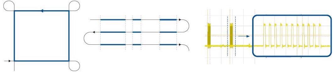
Image Credit: PI (Physik Instrumente) LP
As the cost of picosecond and femtosecond lasers continues to decrease, there is an ongoing expansion in their adoption and application in techniques and material processes.
The boundaries of next-generation use cases continue to be pushed by the advent of new features, higher power and efficient second and third harmonic generation. PI is helping exploit these advances with equally innovative laser motion control solutions that are ideal for evolving next-generation processes.
Advantages of Ultrafast Micromachining over Traditional Machining
Lasers can be utilized as a non-contact localized micromachining method, bypassing traditional machining limitations related to resolution and wear.
Ultrafast lasers also demonstrate effectiveness in the processing of brittle, flexible and composite materials that have traditionally been difficult to machine precisely via classic methods.
Lasers are also able to process below the surface of material via tightly focused beams. This is beneficial in machining flexible displays and other technologies with transparent media, including sapphire and glass.
Dynamic Impact of Mode-Locked Laser Process Performance
When run at fixed pulse repetition frequencies (PRF), material-specific laser process parameters are generally optimized via constant average power and consistent pulse overlap.
Operating at a fixed repetition rate ensures that the consistency of pulse overlap becomes of a function of motion system dynamics potentially in multiple dimensions:
Figure 1a/b. Laser pulse placement under constant velocity motion at fixed rep rate. Here, pulse overlap uniformity is correlated to motion system performance. Shown above is achievable single axis scanning performance using PI V-551 Stages on High Performance A-81x Series Motion Controller with PILOT Tech. Image Credit: PI (Physik Instrumente) LP
Figure 1c/d. Laser pulse placement during acceleration/deceleration on a single axis using fixed rep rate. Here, the pulse overlap uniformity would result in potentially undesirable material effect related to non-uniform power. To address constant pulse overlap on variable dynamics, a Laser Control Interface is used with Fixed Distance triggering to compensate for inconsistent motion. Image Credit: PI (Physik Instrumente) LP
Figure 1e/f/g. Laser pulse placement during multi-axis corner rounding motion using fixed rep rate. Here, the pulse overlap uniformity would result in potentially undesirable material effect especially related to potential HAZ in areas with punched pulses. There are two approaches to address this - essentially using fixed distance pulse picking through dedicated Laser Control Interface, or the advanced trajectory algorithms to run constant vector velocity. Image Credit: PI (Physik Instrumente) LP
Disruptive Technology and Next Generation Laser System Performance
These basic examples illustrate deceptively novel embedded disruptive technology.
Until recently, implementing these features in integrated motion systems for laser tool builders resulted in a range of constraints on system configuration; for example, stage selection, cost, extended, system start up, increased complexity and limited top-end performance.
New Laser Tools
These last-gen approaches required the high-speed motion synchronized laser trigger to be pre-determined. The laser trigger was delivered in an expensive drive module that was limited to the incremental encoder protocols associated with lower performance motion systems, such as square wave (A Quad B) signals.
These requirements substantially lowered the achievable trigger resolution when utilizing higher performance sin/cos encoders.
The use of user-friendly absolute encoders was also restricted. There were limitations around the potential of the virtual axis for best use of gantries and more cost-effective, open-loop, stepper motor stage solutions.
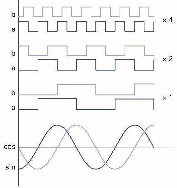
Figure 2. PI motion synchronized laser triggering can use the highest-resolution linear encoders. In previous approaches, such an encoder would either be restricted to trigger on zero crossings or use an external interpolator that would restrict performance and potentially speed. More information on ultra-high-resolution encoders. Image Credit: PI (Physik Instrumente) LP
Flexible Laser Tools
In previous approaches, it was necessary to preconfigure the motion system with expensive drive technology. This often had to be re-configured when the application requirements were altered.
A newer and more disruptive approach facilitated the addition of rapid laser triggering to virtually any system prior to or following delivery via a range of drive technologies.
This new approach is a robust, adaptable solution for linking a laser to multi-axis positioning.
The capacity to synchronize motion with external events is often referred to as position synchronized output (PSO) or position event generation (PEG).
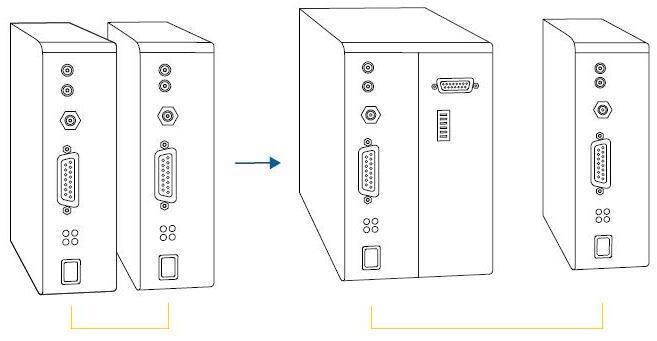
Figure 3. In the past, if laser triggering demands exceeded system capability, the system integrator would have to literally rebuild the entire control system. This may involve the replacement of the first drive unit with a larger, more complex and expensive drive that can address new requirements. Image Credit: PI (Physik Instrumente) LP
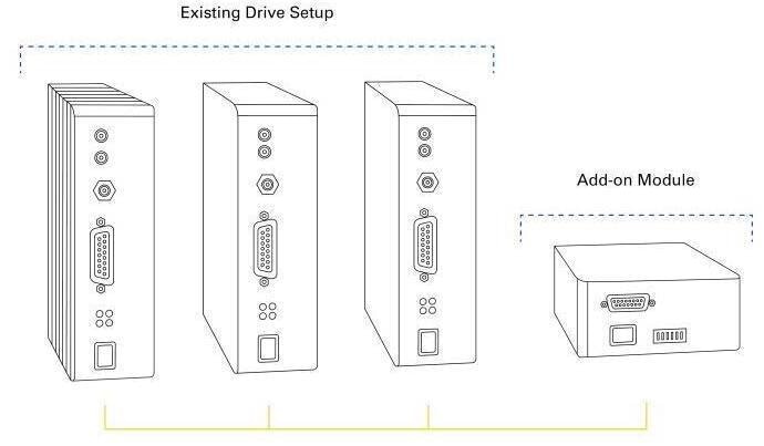
Figure 4a. Now, system configurations are optimized to the application requirements without imposed limitations of specific encoder feedback or drive. If high performance laser triggering is required, it’s merely an add-on module (LCM, shown right) that is configured for the system in minutes. Image Credit: PI (Physik Instrumente) LP
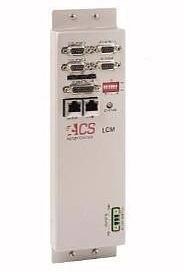
Figure 4b. PI’s modular ACS Laser Control Module. The LCM laser control interface can achieve a max pulse frequency of 10 MHz and multi-axis position-based triggering with sub-micrometer laser pulse accuracy. It provides features such as: Fixed Distance & Array Based Pulse Firing, Dynamic Power Control by Digital Pulse Modulation, Axis Range Windowing, Array Based Gating, Tickle for Maintaining Laser Ready, Delay Compensation, and Combined Modes. Image Credit: PI (Physik Instrumente) LP
User-Friendly, Higher Top-End Performance at Lower Cost
The elimination of constraints on drives, stages and encoder technologies means that systems can be configured to address application requirements without the need to compromise performance or cost-effectiveness.
These new possibilities include the option of using high-performance (sin/cos) linear encoders without additional hardware, therefore, fully leveraging the potential of this state-of-the-art dynamic performance.
So, high speed synchronized laser control can employ state-of-the-art trajectory building, using PI’s proprietary algorithms to help avoid errors. This performance is unique at PI.
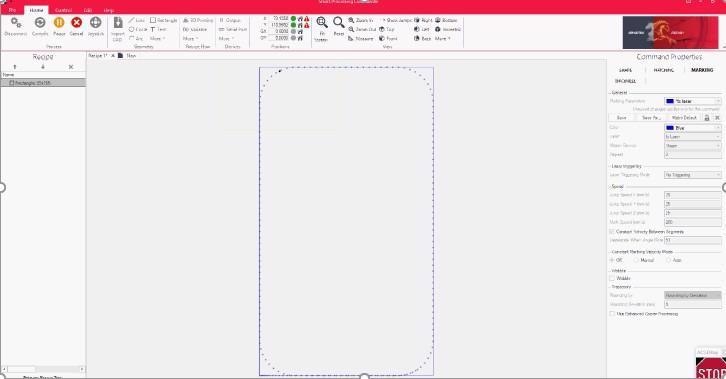
Figure 5a. SPC Laser Materials Process and 3D Print Software taps into PI’s advanced controls capability and stage performance. Shown here is a rectangular motion path created in the software with automatic corner rounding and constant velocity enabled. Image Credit: PI (Physik Instrumente) LP
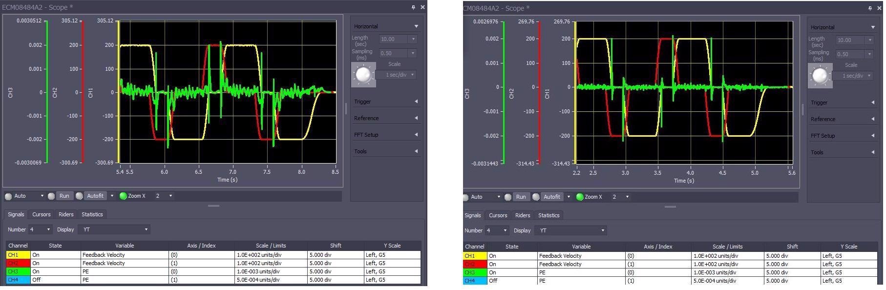
Figure 5b/c. Controller and stage performance: Here we see the performance of two compact, highly dynamic V-508 series linear motor stages in X-Y configuration, tracing a rounded rectangle in a laser cutting application. Left: with PILOT algorithms. Right: without PILOT servo control. The green trace in both plots is the trajectory following error. Image Credit: PI (Physik Instrumente) LP
A key advantage for motion stages in general materials processing and gantry systems stems from employing more user-friendly, contamination resistant and safe absolute linear encoders based on industry-standard protocols; for example, EnDat and BiSS.
Through the use of proprietary advanced gantry control, the legs of a dual encoder or dual-motor gantry axis can be combined to create a virtual linear axis with a dual-theta loop - allowing the use of virtual axis for laser triggering and pulse picking.
This disruptive approach improves accuracy by triggering on the yaw-compensated virtual center axis rather than from either side of the gantry while also eliminating a potential collision that causes homing move.
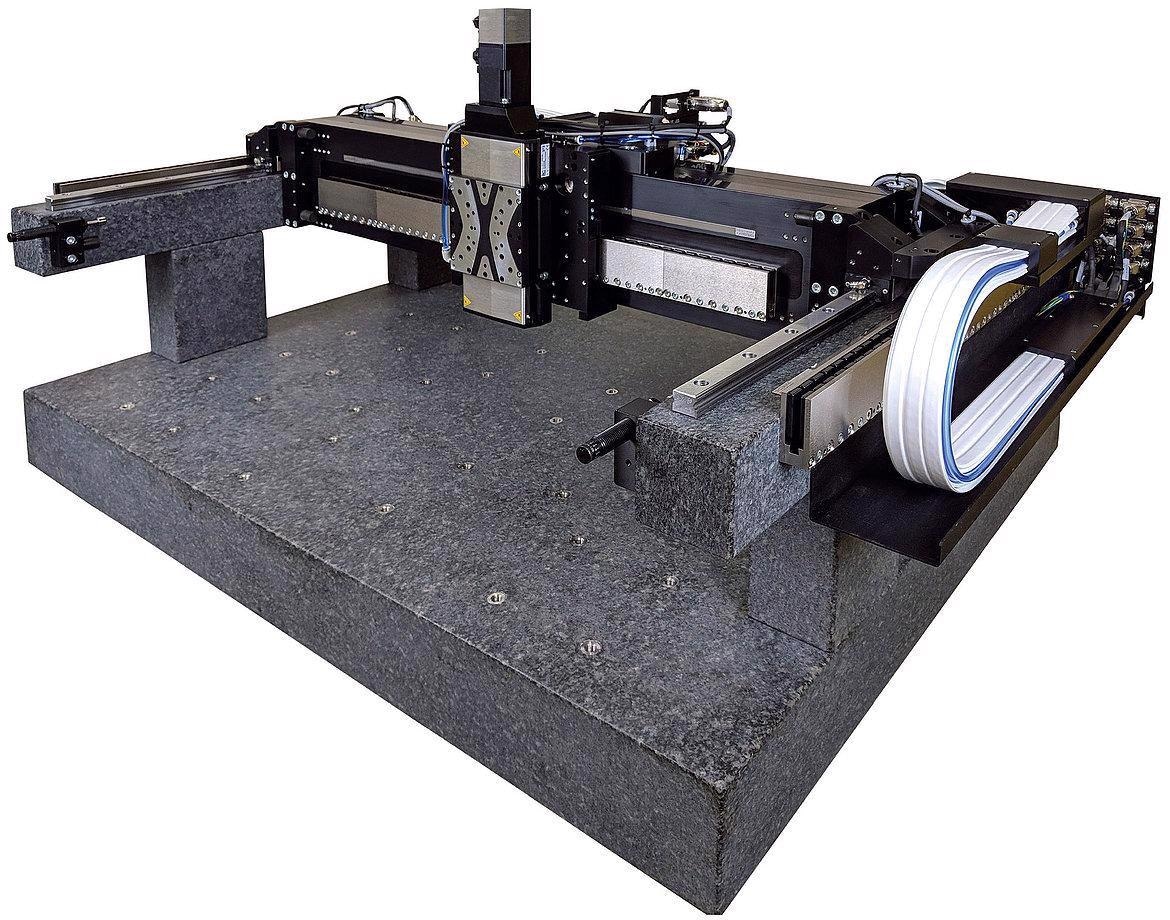
Figure 6. PI A-351 X-Y-Z high speed, high precision gantry stage / linear robot systems come in a large variety (size, base material, bearings, motors,…) and have become a standard for high precision 3D Printing processes with advanced gantry control with coordinated multi-axis synchronized laser trigger on virtual axes. Image Credit: PI (Physik Instrumente) LP
XYZ-Theta Gantry Control & Input Shaping—Advanced Algorithms, Multi-Axis Control in Automation | PI
Advanced Gantry Control Algorithms provide higher precision and throughput. Video Credit: PI (Physik Instrumente) LP
Advanced laser triggering is also possible without encoder feedback, allowing systems to maintain laser triggering while being configured using encoder-free, cost-effective stepper motors.
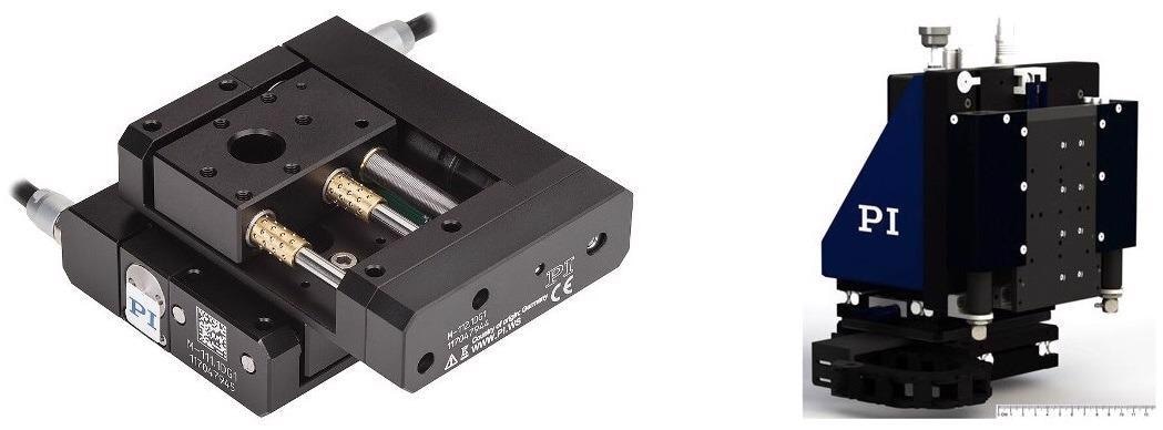
Figure 7a/b. Not all laser processing applications require large positioning stages. The M-111 miniature XY stage, on the left, provides 15x15 mm travel, 5 0nm incremental motion, and is available with stepper and servo motors. The F-408 XYZ stage (right) provides 25x25x25 mm travel and 20 nm incremental motion. It is equipped with linear motors and an air spring counterbalance on the vertical axis. Both systems can now be combined with High-Performance Motion Synchronized Laser Triggering. Image Credit: PI (Physik Instrumente) LP
Laser Machining - Large Area, High Throughput, High Path Accuracy: PI Motion Systems & Controls
Laser machining example – achieving high precision and throughput over large areas by combining a galvo and planar X-Y linear stage. Video Credit: PI (Physik Instrumente) LP
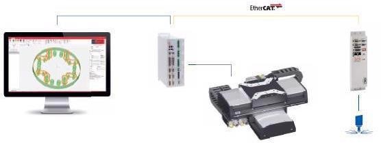
Figure 8. Simple connectivity with Ethernet cables. Image Credit: PI (Physik Instrumente) LP
Automation systems working with laser material processing tool builds must be able to work optimally and flexibly with a range of technologies, including motion synchronized pulsed laser control and triggering (including CW), Flexible Galvo integration, G-Code compatibility and software that can accommodate the direct import of industry standard CAD file formats, such as STL and DXF.
These formats must also be able to work with direct to process 2D and 3D with flexible layering and infill settings.
When used with fixed optics, it is possible to employ direct laser control with multiple high-performance triggering and laser control modes.
This can be utilized in combined options or in a galvo, and it is advisable to work flexibly with a galvo manufacturer to determine the optimal model and optical configuration.
Intuitive, Powerful Laser System Control Software
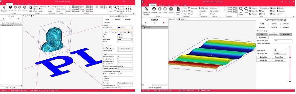
Figure 9 a/b. Here, the most complete commercial laser system software available is shown. The Smart Processing Commander (SPC) includes numerous PI Proprietary features developed in next-gen processes. This Laser System Interface supports integration of multiple galvo-models and manufacturers, machine vision, surface height sensors, autofocus as well as dispensers and extruders for additive manufacturing. Numerous flexible parameters settings allow advanced features to be accessed with simple button pushes. SPC is used in both commercial systems integration and at leading R&D facilities. Image Credit: PI (Physik Instrumente) LP
Summary
High performance ultrashort laser sources have become more affordable in recent years, allowing machine builders and system integrators to implement machining methods with improved performance than traditional approaches.
Laser processing offers a range of benefits, such as improved precision, higher throughput and the capacity to process increasingly minute features.
The majority of processing applications necessitate the use of motion control, for example, gantries, stages, controllers and software.
Advanced connections between laser control and motion control enable flexible, improved synchronization between the firing of the laser and its precise location on the motion path.
Costly solutions with specialized controllers and closed system architectures have been available for some time, but the industry is now adopting networks such as EtherCAT to simplify this process, add functionality and upgrade systems.
This level of connectivity provides significant advantages for machine builders and system integrators, allowing them to select appropriate drivers, controls and motion amplifiers for the motion system.
It also makes it easier to select the most appropriate interfacing option for the laser, providing machine builders and system integrators with straightforward, rapid, accurate and flexible control of laser processing applications.
XY-Theta Stages, Air Bearing Motion Systems for High Precision Laser Dicing / Processing
Air bearing stages in laser processing demo – the EtherCat based motion controller synchronizes laser firing with the planar X-Y air bearing table and rotary air bearing table. Video Credit: PI (Physik Instrumente) LP

This information has been sourced, reviewed and adapted from materials provided by PI (Physik Instrumente) LP.
For more information on this source, please visit PI (Physik Instrumente) LP.