Sponsored by Vitrek, LLCReviewed by Olivia FrostAug 15 2025
This article examines the advanced features of GaGe CompuScope Digitizers in a range of applications.
GaGe CompuScope Digitizer Features for NDT
While ultrasonic Non-Destructive Testing (NDT) tends to be used for material inspection, many of the same CompuScope features also apply to medical ultrasonics. The three most impactful features for ultrasonic applications are:
- High Vertical Resolution: CompuScope digitizers offer high vertical resolution, which significantly improves the ability to detect low-amplitude ultrasonic echoes. In many cases, flaw echoes are extremely small and occur immediately after large wall echoes, making amplification difficult. An 8-bit oscilloscope can only detect echoes larger than 1/256th of a strong wall echo (since 28 = 256). In contrast, a 16-bit digitizer offers a minimum detectability threshold that's 256 times lower, allowing for far more precise echo detection.
- High Sampling Speed: Vitrek recommends a sampling rate of 10× the ultrasonic transducer’s center frequency. With CompuScope models capable of sampling at several GigaSamples per second (GS/s), signals from transducers operating at center frequencies up to several hundred MHz can be captured with ease, covering a broad range of ultrasonic applications.
- High Data Transfer Speed: CompuScopes can transfer data to a host PC at over 5 GB/Second via the PCI Express interface. This allows users to capture ultrasonic triggers at rates above 100 kHz. Faster transfer speeds translate to shorter scan times in ultrasonic imaging and higher time resolution in dynamic signal analysis.
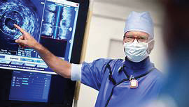
Image Credit: Vitrek, LLC
Additional CompuScope features valuable for ultrasonic applications include:
- Multiple Record mode, which enables rapid re-arming—within a microsecond—for high trigger rates.
- Signal averaging, which reduces random noise and improves the visibility of very small echoes.
- Trigger output, which eliminates jitter from asynchronous sampling during ultrasonic pulse reception.
Streaming with Rapid Ultrasonic Triggers
Building on the capabilities outlined above, CompuScope digitizers also support real-time data streaming in fast-paced ultrasonic environments.
While many streaming applications rely on a single trigger to initiate continuous waveform recording over extended periods—often lasting minutes or even hours—ultrasonic testing frequently presents a different challenge. Instead of a single long acquisition, users often encounter an endless stream of ultrasonic triggers, each requiring fast and precise waveform capture.
Fortunately, GaGe CompuScope digitizers are well-suited for this type of application. Even when dealing with high-frequency, repetitive ultrasonic triggers, users can still take full advantage of the CompuScope's streaming capabilities by operating in Multiple Record mode.
In this mode, the digitizer captures short waveform segments—typically just a few thousand points—then re-arms itself in under one microsecond to prepare for the next trigger. This approach allows for highly efficient data acquisition, enabling users to stream data continuously without being overwhelmed by unnecessary information between events.
By suppressing non-essential data between triggers, Multiple Record mode not only maintains high transfer efficiency over the PCI Express bus but also ensures that critical signal details are captured with precision, even in applications with extremely high trigger rates.
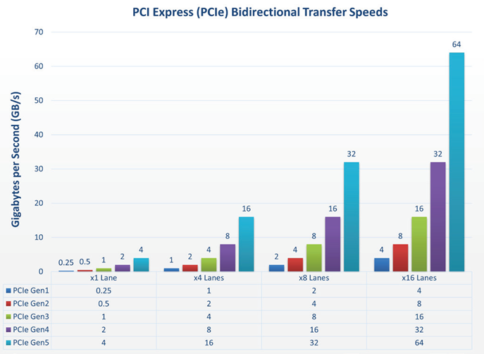
PCI Express (PCIe) Bidirectional Transfer Speeds in Gigabytes per Second (GB/s) for each Generation. Image Credit: Vitrek, LLC
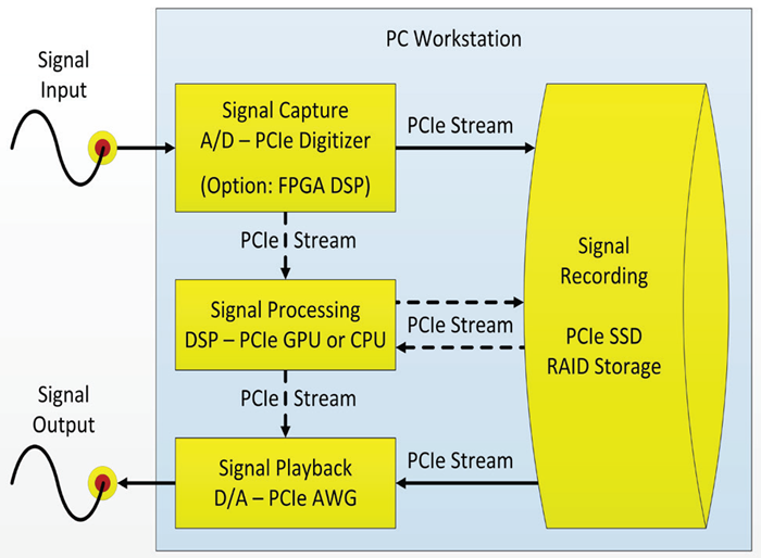
Building Blocks of Real-Time High-Speed Data Acquisition System with Integrated PCIe Instruments. Image Credit: Vitrek, LLC
Synchronizing Multiple CompuScope Digitizers for High-Channel Ultrasonic Sampling
As testing complexity increases, some applications demand more channels than a single CompuScope digitizer can provide. Fortunately, synchronization makes it possible to scale.
While the GaGe Sabre CompuScope offers four channels with sampling rates up to 250 MS/Second, some applications, such as advanced ultrasonic testing, require simultaneous acquisition across more channels. For instance, sampling 12 channels at 250 MS/Second is entirely possible by synchronizing three RazorMax 4-channel CompuScopes.
The CompuScope Software Drivers support any number of installed digitizers within a single PC, allowing them to operate either independently or in synchronized configurations. To enable simultaneous multi-channel acquisition, both sample clocks and trigger signals must be aligned across all digitizers—achievable through external wiring.
There are two common approaches to synchronizing trigger signals:
- Fan-Out Method: A single external trigger signal is split into multiple copies and routed to each CompuScope’s trigger input. This minimizes latency differences between devices, ensuring near-simultaneous activation.
- Cascade Method: The trigger signal is sent to the first CompuScope, which then triggers the second via its Trigger Out, and so on. This daisy-chain method is particularly effective in applications requiring extremely fast trigger propagation across devices.
Sample clock synchronization can also be achieved using two approaches:
- Clock Fan-Out: A single sampling clock (either an external clock at the full sampling rate or a 10 MHz reference signal) is distributed to all digitizers' Clock In inputs.
- Reference Clocking: While a direct high-frequency sampling clock offers the best short-term phase stability, a 10 MHz reference clock is often easier to generate and maintain, and sufficient for many synchronized applications.
Using a CompuScope as a Spectrum Analyzer
In addition to time-domain acquisition, CompuScope digitizers can also support frequency-domain analysis, offering functionality similar to conventional spectrum analyzers.
Spectrum analyzers are generally categorized into two types: swept-tuned and Fourier Transform spectrum analyzers. The latter is essentially a digitizer that applies Fourier transformations to acquired waveform data.
GageScope, GaGe's flagship oscilloscope software, includes built-in Fourier analysis (FFT) capabilities and can be used to operate a CompuScope in the same way as an FFT-based spectrum analyzer. A CompuScope can also be configured to function as a swept-tuned spectrum analyzer, though this setup requires a down-converter to be installed in the signal path.
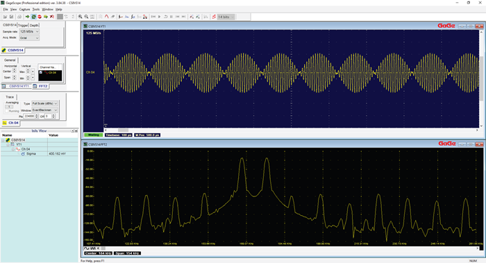
Image Credit: Vitrek, LLC
Understanding Jitter in CompuScope Recordings
To ensure precise timing in measurements, understanding how jitter arises is essential, especially in lower sampling rate setups.
Jitter observed in recorded signals—especially more pronounced at lower sampling rates—is not a sign of failure in the CompuScope hardware or signal configuration. Rather, it typically results from an asynchronous relationship between the sampling clock and the signal trigger.
This condition often produces one-sample jitter in the captured waveform. The effect becomes more noticeable at lower sampling rates because the sampling interval increases, which amplifies the apparent timing variation in the data.
For example, at a sampling rate of 1000 MS/Second, the expected jitter is around 1 nanosecond. Reducing the rate to 100 MS/Second increases the jitter to approximately 10 nanoseconds, due to the longer time between samples.
Programming Environment Support for CompuScope SDKs
To complement its powerful hardware, GaGe offers flexible software integration across multiple development platforms.
GaGe provides comprehensive Software Development Kits (SDKs) for popular programming environments such as C, LabVIEW, and MATLAB, enabling users to fully program and control their CompuScope digitizers. Beyond these, additional support is available for a wider range of environments.
The GaGe C/C# SDK is compatible with C, C++, and C# within the .NET framework. It includes a variety of sample applications and complete project files for each of these languages. C-language support is available for both Windows and Linux operating systems.
Because the CompuScope drivers are written in C, the C/C# SDK delivers the broadest set of sample programs and the highest performance among the available SDKs. While the SDK comes with full project files for Microsoft Visual Studio on Windows, other compilers can be supported with minimal adjustments.
The C/C# SDK also extends functionality to the Python programming environment and serves as a strong foundation for integrating CompuScope into unsupported environments such as Visual Basic. In these cases, users can enable support by calling the GaGe driver DLL using the same method and sequence found in the C sample applications.
Image Credit: Vitrek, LLC
Using the 10 MHz Reference Clocking Feature on CompuScope
Accurate synchronization across systems is often crucial. In situations where high-speed clock signals are unavailable, the 10 MHz reference input offers a practical alternative.
One method for synchronizing an external signal with a CompuScope’s sampling rate is to supply a high-speed external clock signal directly to the digitizer’s ADC chips. However, such high-frequency synchronized clock signals are not always readily available.
Many signal sources do, however, provide a synchronous 10 MHz reference output. This reference signal can be connected directly to the CompuScope, allowing it to internally synchronize its sampling rate to the reference. For instance, if the CompuScope is operating at a 500 MHz sampling rate, it will lock to exactly 50 times the 10 MHz reference input frequency.
This configuration ensures that the phase relationship between the signal and the sampling clock remains stable over time, preventing phase drift and maintaining long-term timing accuracy.

This information has been sourced, reviewed and adapted from materials provided by Vitrek, LLC.
For more information on this source, please visit Vitrek, LLC.