Sponsored by MKS NewportReviewed by Olivia FrostAug 26 2026
An automated motion control system is made up of three major components: a motion controller, a motor driver or amplifier, and a motion device.
The basic function of a motion controller is to regulate the dynamics of the motion device, while the motor driver turns the motion controller's command signals into power signals that move the motor. A motion device is any mechanical device that generates motion and is powered by a motor.
Such motion devices often include feedback devices that provide information to the motion controller, such as position and velocity.
In this article, motion devices are discussed first, mostly in the context of manual placement. This discussion applies equally to automated positioning and motorized drivers. After this, electronic controllers are described.
Motion Devices
Motion devices are mechanical positioning systems that include linear translation stages, rotation stages, and linear actuators. While stage or actuator characteristics are significant selection criteria, they may not be exhaustive or immediately applicable to all applications.
As a result, a thorough understanding of the inherent abilities of the stage's components is essential. This article includes a brief description of the most typical components used in high-precision positioning equipment, along with their benefits and drawbacks.
A motion device's key components are the materials used to make the body, the mechanism that allows for translation or rotation, and the drive mechanism.
Each material utilized for mechanical components in motion control has its own set of advantages and limitations.
Table 1 summarizes the features of the most widely used materials in motion mechanics. Stiffness is a measure of the force required to generate a specific amount of deflection. Young's modulus is a material-dependent constant that measures stiffness, with higher values indicating more stiffness. Thermal expansion is the change in the size or shape of an item, such as a stage, caused by temperature changes (increases or decreases).
When temperature changes across a component are not uniform, for example, when a heat source such as a laser diode is present, a material that does not dissipate heat may be prone to distortions induced by thermal gradients.
In this case, relative thermal distortion, or the ratio of thermal expansion coefficients to thermal conductivity, is crucial, with lower values desirable.
Aluminum is a lightweight material with a strong stiffness-to-weight ratio and minimal thermal distortion. It is also fast-machining, inexpensive, and rust-resistant. Anodized surfaces, on the other hand, are very porous and thus unsuitable for use in high vacuum.
Steel has excellent rigidity, material stability, and moderate thermal expansion, making it ideal for high-vacuum applications. However, steel is substantially slower to machine than aluminum, making steel components significantly more expensive. Though steel corrosion is a severe issue, stainless steel alloys can help alleviate this.
Brass is a thick material that machines quickly and is mostly used for wear reduction, since it can prevent self-welding effects with steel lead screws or shafts. Brass has a low stiffness-to-weight ratio and poor thermal expansion and conductivity qualities.
Granite is a very hard material that can be polished to very flat surfaces, which helps with overall system placement precision and repeatability. Granite also has an extremely low thermal expansion coefficient. However, for huge buildings and table tops, the mass of a granite construction might become impractically heavy.
Table 1. Properties for common stage materials. Source: MKS Newport
| Parameter |
Steel |
Aluminum |
Brass |
Granite |
Young's Modulus (stiffness), E,
Mpsi (GPa) |
28 (193) |
10.5 (72) |
14 (96) |
7 (48) |
| Thermal Expansion, a (µin/in/°F) |
5.6 |
12.4 |
11.4 |
4 |
| Thermal Conduction, c (BTU/hr-ft-°F) |
15.6 |
104 |
67 |
2 |
| Specific Stiffness, E/ρ |
101 (25.4) |
108 (27.7) |
45.6 (11.3) |
70 (17.8) |
| Relative Thermal Distortion, a/c |
0.36 |
0.12 |
0.17 |
2 |
| Density, ρ, lb/in3 (gm/cc) |
0.277 (7.6) |
0.097 (2.6) |
0.307 (8.5) |
0.1 (2.7) |
The type of bearing or flexure used has the most influence on a translation or rotation stage's load and trajectory performance. Bearings are the chosen mechanism because they provide smooth, low-friction rotary or linear movement between two surfaces.
They are the major elements that determine a stage's runout errors, as well as its stiffness and static load capability. Bearings use either a sliding (dovetail) or rolling action (ball or crossed-roller), as shown in Figure 1.
For effective functioning, both bearing surfaces must be separated by an oil or other lubrication coating. Dovetail slides are generally used for manual positioning and consist of two flat surfaces that slide against one another.
They can provide long travel and have a reasonably high rigidity and load capacity. However, they have considerable stiction, which changes with translation speed, making exact control difficult and limiting sensitivity.
Ball-bearing slides reduce friction by converting sliding action into rolling motion. Balls are limited by vee-ways or hardened steel rods, and friction is minimal, resulting in exceedingly smooth movement.
Because the contact area available to transmit loads is smaller in vee-groove bearing systems, ball bearings have a lower load capacity than crossed-roller or other bearings. To carry the same load, the balls would need to be larger in diameter or in greater number.
Crossed-roller bearings provide all of the benefits of ball bearings, but with increased load capacity and rigidity. This is the outcome of using a cylindrical roller's line contact instead of a spherical ball's point.
Because of the averaging characteristic of line contacts, angular and linear deviations are often fewer than those of ball bearings. However, crossed-roller bearings necessitate greater care during manufacturing and assembly, resulting in higher prices.
A flexure mechanism provides translation through the elastic deformation of a material (usually a high-strength steel spring). This mechanism does not require lubrication and is practically free of the stiction that is typically associated with bearings. However, when employed in a translation step, the travel distance is limited to a few millimeters.
Care must also be taken to prevent irreversible deformation, which would result in diminished functionality. In addition to mechanical bearings, air bearings can be used to provide a low-friction surface using a thin film of pressurized gas.
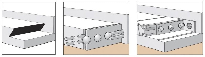
Figure 1. Different types of bearing mechanisms allowing for stage motion: dovetail (left), ball-bearing slide(middle), and cross-roller bearing (right). Image Credit: MKS Newport
A stage can be operated directly by a motor (see below) or indirectly through various mechanical systems (Figure 2). A frequent method for shifting loads is to use the axial translation of a nut riding on a rotating screw. Lead screws have a sliding contact; therefore, their wear rate is directly proportional to usage.
Lead screws have several advantages, including self-locking ability, low-noise motion, inexpensive startup costs, ease of fabrication, and a wide range of materials.
To eliminate any backlash between the screw and the nut, the nut must be preloaded onto the screw using an external spring, gravity forces (only applicable for vertical use), or a double nut with a spring between.
Recirculating ball screws are essentially lead screws with a train of ball bearings riding and rolling between the screw and the nut on a track. Using ball screws reduces screw heating, which improves stage repeatability and accuracy.
Owing to the lower friction, most ball-screw stages may operate at greater speeds and with fewer incremental motions than lead-screw-driven stages.
The large number of mating parts necessitates tight tolerances, raising manufacturing costs. Ball screws also make more noise than lead screws because of the recirculating balls in the nut. The worm gear system converts rotary motion from one plane to another by meshing a screw (worm) with a gear (worm wheel).
As the screw is turned, the worm threads engage with the gear, forcing it to revolve. Worm drives are a popular choice for rotating stages because they allow for a very low-profile design.
To eliminate backlash, the worm and worm wheel must be in perfect contact, necessitating the use of a complex worm preloading mechanism with high transversal rigidity.
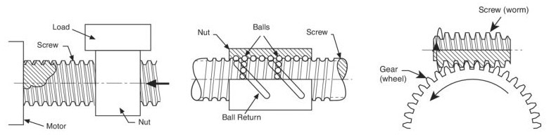
Figure 2. Different mechanisms for indirectly driving a stage: lead screw (left), ball screw (middle), worm drive (right). Image Credit: MKS Newport
Actuators (Figure 3) can also be used to drive a stage indirectly, but they are normally externally connected, allowing for greater flexibility in matching a specific stage to the desired drive mechanism.
Manual actuators are simple, low-cost positioning alternatives that resemble a high-sensitivity lead screw with a knurled knob. Unlike the lead-screw arrangement mentioned above, the screw's nut is attached to the stage body, but the adjustment screw swings back and forth.
Springs force the carriage against the screw tip, ensuring solid contact, preloading the screw, and eliminating backlash. Micrometer heads are the preferred adjustment mechanism for accurate position readout or repeatable positioning.
Standard metric micrometer heads have a 10 µm scale but can achieve 1 µm precision with an extra vernier. When resolution of less than one micron is required, a differential screw is recommended. These devices generate highly precise motion by leveraging the differential between two screws with virtually identical pitch.
Motorized linear actuators can be used to motorize manual linear translation stages and control them remotely or via computer. Such actuators can use either the lead screw mechanism described above or the piezoelectric effect, which uses interactions in specific crystalline materials to generate mechanical movement when an electric field is applied.
These piezo actuators, also known as nanopositioners, have a resolution of a few tens of nanometers. This improved resolution usually comes at the expense of diminished speed and/or travel distance.
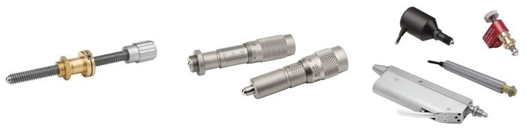
Figure 3. Various types of actuators including a manual actuator (left), a micrometer (middle), and motorized actuators (right). Image Credit: MKS Newport
Motorized Drivers
A motion device can be electrically controlled using a direct or indirect motorized drive system.
Common indirect-drive systems for linear and rotary stages are built on the lead screws, ball screws, and worm drives outlined in the previous section. Shaft couplings, transmission belts, and gearboxes are commonly found between the drive system and the driving motor.
These components influence system dynamics such as speed and torque capacity, but they can also cause backlash and hysteresis. The two most prevalent motors used in indirect drive systems are brushed DC motors and stepper motors.
A brushed DC motor comprises a rotor in a magnetic field that rotates when electricity is delivered to the motor windings. The rotational speed is proportional to the applied voltage, and the torque is proportional to the current. DC motors are best known for their smooth action and fast speeds.
A stepper motor operates on the basic concept of magnetic attraction and repulsion. Steppers translate digital pulses to mechanical shaft rotation. The quantity of rotation is proportional to the number of input pulses generated, while the speed is proportional to pulse frequency.
A DC servo motor produces both torque and spin when a voltage is applied to it, which distinguishes it from a stepper motor. However, when a voltage is applied to a stepper motor, it produces only torque. To cause the stepper motor to revolve, the current applied must be commutated or switched.
Stepper motors are commonly used in open-loop control systems, which are a cheaper alternative to closed-loop DC servo systems. The pulse count is an accurate measure of position, and stepper motors perform reliably when used within their torque and speed ranges.
Outside its specified range, a stepper motor's action becomes unpredictable and may skip steps, take extra steps, or stall. Stepper motors typically generate torque almost instantly, faster than a DC brush motor.
As a result, stepper-motor-driven stages can handle mechanical stiction better than DC-motor-driven stages, which frequently produce position overshoots when the motor torque exceeds the stiction.
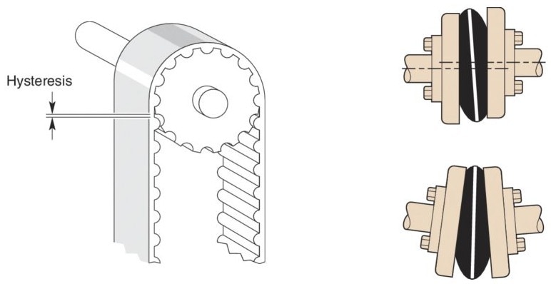
Figure 4. Components for connecting the drive system and the driving motor, including a belt drive (left) and a flexible shaft coupling (right). Image Credit: MKS Newport
In direct-drive systems, the motor is directly connected to the motion, with no screw or transmission mechanism in between. The most popular high-precision direct-drive systems use a brushless linear motor for linear stages and a brushless torque motor for rotational stages.
A linear motor is made up of a permanent magnet assembly that creates a magnetic flux and a coil assembly that produces a force proportionate to the coil current. Linear motors have become critical components of precision positioning systems, offering various advantages over traditional mechanical actuators such as ball screws.
These systems often offer better quality, frictionless motion, and faster speeds and acceleration.
A motor driver takes input signals from a controller and turns them into electricity to run a motor. A motor driver might be a basic amplifier or a sophisticated device with software-configurable operational settings. Different motor drivers support the different types of motors used in motion control.
The motion controller sends input signals to the stepper-motor driver, instructing it to move the motor to a specific position. The driver then sends current through the stepper motor windings to advance the stepping motor to the next step or increment.
Drivers for DC motors simply convert the motion controller's -10 V to +10 V analog control signal into a usable current to power the motor. Most brushless DC motor drivers are simply amplifiers that translate control signals from the motion controller into usable current to operate the motor, while the motion controller handles motor commutation.
Electronic Controllers
In a motion system, the controller manipulates stages and actuators to cause them to move or stop in the desired manner. Common motion-control methods include position control, velocity control, and torque control.
Each control method is based on a feedback device, which transforms a physical characteristic, such as a scale reading, into an electrical signal that the controller may use. Most motion systems employ the position-control approach.
In these systems, the motion controller commands a motor so that the actual position of the moving mechanism corresponds to the desired position indicated by a preplanned trajectory.
In this scenario, the primary feedback device is an encoder, which directly monitors position and gives actual displacement information to the motion controller. Typically, this is accomplished optically by sensing light traveling through a series of precisely spaced slits on a metal or glass disk (Figure 5).
Velocity control is used in applications that require precise velocity regulation, such as spindles or conveyor belts. In these situations, a tachometer is the primary feedback device.
Torque control is employed in applications such as robotics, where end-effector torque must be precisely controlled to grip or release objects. In these cases, the principal feedback device is a torque/force sensor, such as a strain gauge.
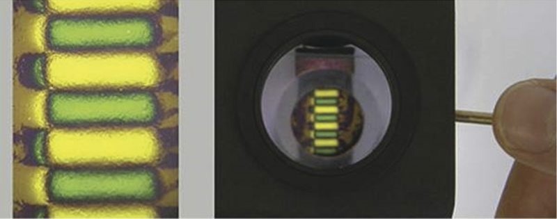
Figure 5. Example of a linear steel scale encoder that ensures positioning with accuracy of ±1 µm. Image Credit: MKS Newport
While the primary purpose of a motion controller is to operate a motion device, many modern motion controllers provide extra abilities, such as:
- Trajectory generation for moving items or coordinating their motion
- Configurable and instructable motion system to accomplish different tasks
- Monitoring end-of-travel limitations, amplifier faults, and feedback mistakes to ensure system safety
- Digital input/output lines synchronize external events with movements or vice versa
- Memory for on-board motion programs
The output of the motion controller can be customized based on the type of motor used to operate a motion device.

This information has been sourced, reviewed, and adapted from materials provided by MKS Newport.
For more information on this source, please visit MKS Newport.