Chemical Mechanical Planarization (CMP) is a critical process in the semiconductor, LED wafer, and hard disk manufacturing industry and is used to achieve the substrate wafer's required planarity. Planarization is vital when it comes to ensuring the functionality of the multi-level interconnects within the structures and reducing wafer thickness while maintaining uniformity.

Image Credit: Sensofar Metrology
CMP is thought to serve an increasingly important role in the future development of microelectronic devices as feature sizes continue to shrink and integration levels continue to increase. By accurately regulating the material properties and surface topography, CMP can facilitate new device architectures, such as finFETs, 3D stacking, quantum dots, and nanowires.
Moreover, Chemical Mechanical Planarization can also be used to facilitate new material integration, such as high-k dielectrics, low-k dielectrics, copper, cobalt, graphene, and carbon nanotubes, by overcoming the limitations of conventional etching techniques.
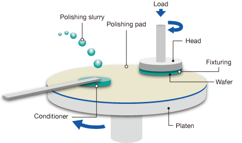
Figure 1. CMP process schematic diagram. Image Credit: Sensofar Metrology
How Does CMP Work?
CMP integrates mechanical and chemical forces on a semiconductor wafer to eliminate excess material and form a smooth, flat surface. It is an important approach for attaining high-performance and high-quality microelectronic devices. CMP is broadly utilized in the industry for different applications, like:
- Planarizing interlayer dielectrics (ILDs) and metal layers in integrated circuits (ICs) to minimize parasitic capacitance, enhance reliability, and facilitate multilevel interconnects.
- Planarizing shallow trench isolation (STI) structures to prevent leakage currents and separate active devices.
- Planarizing silicon-on-insulator (SOI) substrates minimizes power consumption and improves device performance.
- Planarizing microelectromechanical systems (MEMS) to enhance functionality and integration with ICs.
- Planarizing magnetic disks and read/write heads for computer hard drives to improve storage density and data transfer rate.
As part of the CMP process, the wafer is held on a rotating fixture and pressed against a rotating polishing pad. An abrasive chemical liquid (called slurry) is then distributed between the wafer and the pad. The chemical slurry weakens the wafer’s surface, enabling the removal of material by the asperities of the pad. This process is then repeated until the user has achieved their desired planarity level.
CMP is a challenging and complicated process that involves several parameters, such as pad material, slurry composition, velocity, pressure, temperature, and endpoint detection. The surface properties of the polishing pad play a particularly important role in the final quality of the CMP process, as they can impact the amount of material eliminated from the wafer.
As the polishing pad degrades during the polishing process, it has to be continuously reconditioned. This is typically conducted via an abrasive process on the pad surface, using a rotating abrasive or conditioning disk made of stainless steel or electroplated diamond.
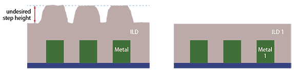
Figure 2. Cross-section diagram of internal dielectric on top of metal line before and after CMP. Image Credit: Sensofar Metrology
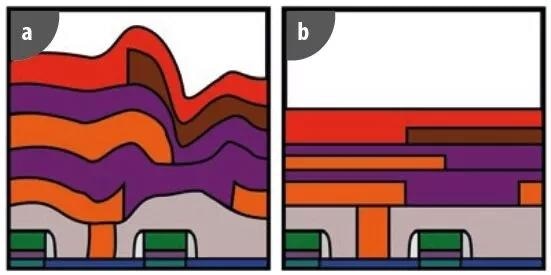
Figure 3. Wafer manufacturing (a) without CMP and (b) with CMP. Image Credit: Sensofar Metrology
Surface Metrology for CMP
The key to the success of the Chemical Mechanical Planarization (CMP) process lies in Surface metrology, as the mechanical communication between surfaces is an important variable for all stages in the process. The surfaces that tend to require periodic characterization throughout the CMP process include the conditioning disk surface, the wafer surface, and the pad surface.
In high-volume production environments, non-destructive in-situ pad characterization is vital during natural pauses in the polishing process, such as when changing wafers. This allows for the detection of drifts in major pad parameters and helps to validate process changes. The ultimate goal, however, is to extend the lifetime of consumables and enhance process yield, which is a vital part of any successful manufacturing operation.
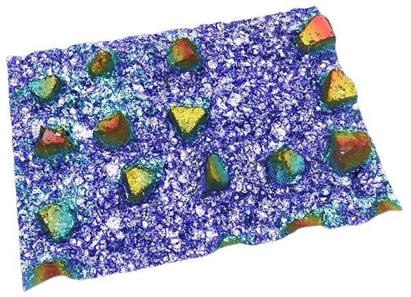
Figure 4. 3D topography of conditioning disk surface. Image Credit: Sensofar Metrology
Two main factors affect pad surface degradation and lifecycle; pad groove occlusion and pad glazing.
Groove Occlusion
Throughout the polishing process, the material removed from the wafer settles in the pad grooves, resulting in occlusion. This phenomenon prevents the even distribution of slurry throughout the wafer, resulting in uneven removal between the edge and the center of the wafer.
When it comes to cleaning the pad grooves and determining the best time for cleaning, groove occlusion monitoring is necessary. Cleaning operations can extend pad lifetime by up to 20%.
Pad Glazing
Pad glazing is a more complicated phenomenon that happens when the polishing capacity of the pad is minimized as a result of surface degradation. This phenomenon improves wear between the pad and wafer, increasing process temperature and ensuring material selectivity during polishing.
Contrary to groove occlusion, pad glazing cannot be easily predicted and requires constant monitoring to ensure the ideal performance of the CMP process.
In-situ pad surface monitoring is important for both pad glazing and groove occlusion. Thus, the metrology method employed must be able to function in wet conditions. Immersion metrology is the sole method that can fulfill these needs.
The key advantage here is that the pad does not need to be removed from the polisher for characterization. This means that pad glazing and groove occlusion can be monitored in situ at different points throughout the pad’s life cycle. In-situ metrology has successfully proven to extend pad lifetime, enabling operators to use the pads until the end of their useful life.
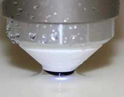
Figure 5. Immersion objective. Image Credit: Sensofar Metrology
In-Situ Immersion Metrology System
Several years ago, Sensofar embarked on a collaborative journey with industry specialists to build a state-of-the-art surface metrology solution for the CMP process. The objective was to maximize yield per pad and reduce polishing system downtime by enabling pad changes only when required. S mart 2, a non-destructive, in-situ 3-in-1 surface metrology system, was the outcome of this collaboration.
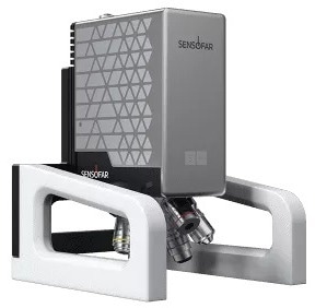
Figure 6. S mart 2, portable areal confocal head. Image Credit: Sensofar Metrology
Using S mart 2, users can rapidly test the status of the polishing pad using a portable stand; the sensor can be placed on the pad while it is still inside the polishing system. The new head is designed to be lighter and more compact. It has an embedded electronic controller that makes it a plug-and-play system with only two cables (power and communication) exiting the head.
The S mart 2 system can be operated directly from a laptop, in turn improving convenience and portability. It can also be integrated into a production line as an automatic metrology solution or used as a standalone system. Using S mart 2, users can quickly obtain and explore data to efficiently track critical pad features like glazing and groove occlusion.
The earlier version of S mart has already demonstrated that CMP pads were being under-utilized and usually discarded when they still had about 50% of their lifetime remaining. With the introduction of S mart 2, tracking pad conditions and extending their lifetime efficiently is now even easier.
S mart 2 for CMP Monitoring
S mart 2 comes with Sensofar patented technology and a high-intensity blue LED, which combines Confocal, Ai Focus Variation, and Interferometry technologies within a single sensor.3 Within the S mart 2 control interface, the SensoPRO software plugin - which is built around the CMP application - offers all the necessary tools and analysis for this application.
The S mart 2 sensor provides a unique metrology approach that, when paired with an appropriate immersion objective, allows for the accurate measurement of pad asperities even while still on the polisher.
Monitoring Groove Occlusion
By utilizing Confocal and Ai Focus Variation technologies, groove depth and width can easily be detected and monitored, allowing for efficient identification and tracking of groove occlusion. For production environments, a SensoPRO software plugin can be used for automatic analysis, independently determining the groove’s width and depth, regardless of its orientation.
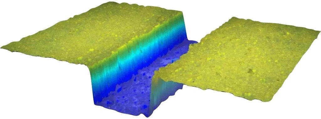
Figure 7. 3D measurement of a new pad groove. Image Credit: Sensofar Metrology
Pad Glazing Monitoring
S mart 2 and its Confocal technique - which is compatible with water immersion conditions - can characterize pad asperity after conditioning and polishing phases rather effectively. Monitoring is also one of the best ways to determine the pad’s condition - it can also be useful when it comes to establishing the best time for conditioning and the optimal duration needed to regenerate the pad surface. These capabilities help prolong the pad’s usable lifespan, minimize the need for control wafers, and optimize the overall process, preventing the need for re-processing of finished wafers.
The image below outlines how the asperity height of the pad alters at the time of polishing.
As polishing takes place for several hours, a “glazing peak” can be seen in the distribution of the surface. Monitoring the pad surface at intervals throughout the process means that the user can intervene and condition the pad surface to revert it back to its initial state. This information can be used to help optimize any polishing process to achieve consistent results.
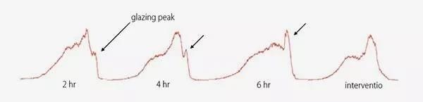
Figure 8. Image showing evolution of the pad asperity height during the polishing process. After several hours of polishing a ‘glazing peak’ appears in the surface distribution. By monitoring the pad surface at intervals during the polishing process, the pad surface can be duly conditioned (intervention) in order to revert the surface condition to the initial state. Image Credit: Sensofar Metrology
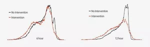
Figure 9. Image showing comparison for the pad before intervention (black) vs the pad following intervention (red). The image on the left side was for the surface after a 6-hour polishing process, and the right one is after 12 hours. Image Credit: Sensofar Metrology
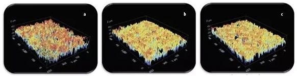
Figure 10. (a) New pad; (b) Good pad after 10 hours of use; (c) Bad pad after 3 hours of use. Image Credit: Sensofar Metrology
Automatic Analysis
The precise control of surface parameters is made easy through the S mart 2 sensor. The analysis of obtained data can be automated, enabling operators to position the sensor over the pad's surface, obtain the measurements, and acquire a report. The SensoPRO software automatically shows the target parameter value and the pass/fail report for the specific tolerance, simplifying the process and minimizing the possibility of errors.
SensoPRO is a robust tool for quality control managers, facilitating direct comparison between datasets and the demonstration of automatic tolerances for CMP monitoring. Using SensoPRO, users can easily and quickly compare and analyze data, guaranteeing consistent quality and process control.
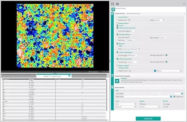
Figure 11. Software screenshot example. Image Credit: Sensofar Metrology
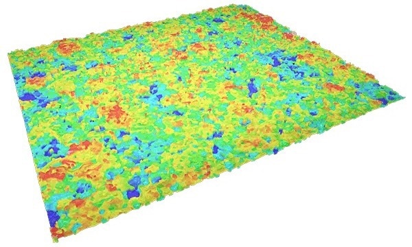
Figure 12. Topography example. Image Credit: Sensofar Metrology
Conclusions
CMP ensures the planarity and functionality of structures built on a wafer. With advancing technology, CMP is becoming increasingly important, meaning that it is a critical area of focus for researchers and manufacturers.
In this context, in situ surface measurement is vital for monitoring the CMP process, minimizing costs, and ensuring quality.
Sensofar’s new S mart 2 provides advanced acquisition and analysis tools to support CMP research and quality control. By taking advantage of S mart 2's advanced capabilities, manufacturers and researchers can optimize their CMP processes, achieve superior results, and stay ahead in a rapidly evolving industry.
References and Further Reading
- Mahadevaiyer Krishnan, Jakub W. Nalaskowsk, and Lee M. Cook, “Chemical Mechanical Planarization: Slurry Chemistry, Materials, and Mechanisms” Chem. Rev., 2010, vol. 110, pp 178–204.
- Zhengfeng, Wang, Yin Ling, Ng Sum Huan and Teo Phaik Luan. “Chemical Mechanical Planarization.” (2001).
- J. McGrath, C. Davis. Polishing pad surface characterization in chemical mechanical planarization. Journal of material processing technology, 153-154 (2014).
- T. Moore, N. Schwarz. NEOX Ex-Situ CMP Pad. NCCAVS, CMP Users Group Proceedings (2013).
- R. Artigas, F. Laguarta, C. Cadevall. Dual-technology optical sensor head for 3D surface shape measurements on the micro- and nanoscale. Optical Metrology in Production Engineering, Proc. SPIE 5457 (2004).

This information has been sourced, reviewed and adapted from materials provided by Sensofar Metrology.
For more information on this source, please visit Sensofar Metrology.