Introduction
Sintered Al2O3 ceramics are an attractive material for functional or high temperature application because of their excellent properties such as high strength, oxidation resistance, thermal shock resistance and wear resistance [1]. However, its excellent properties are reasons for the material to be difficult to machine. Shen et al. calculated the percentage of the machining cost of ceramics, and concluded that the value would be about 80% or more of the total component cost in the industrialized world [2]. Until now several kinds of machining method such as laser machining [3, 4], abrasive jet machining [5, 6] have been suggested to reduce machining cost of ceramics. These machining methods, however, generate defects in machined surface layers. A grinding process with diamond grinding wheels is the most common method [7]. Grinding is widely used as an efficient and effective technique for a finishing process of ceramic materials, and is an important machining operation for producing modern equipment using advanced materials. A grinding process inevitably generates both brittle fractures and ductile flaws as diamond abrasive grains cut into ceramic specimens [8, 9]. A surface machining process, such as conventional grinding and lapping, introduces damages into ground surface layers of ceramic materials [10-12]. Excessive forces during the grinding process generate defects such as chips, cracks, flaws, and/or fissures. The grinding defects decrease the strength of ceramics [13, 14]. A few researchers reported that the size of machining damage reached from several tens of micrometers to several hundreds of micrometers [15, 16]. For removing damaged layers, heat treatments or etching processes are normally required [17, 18].
For a conventional grinding system grinding depths and table-feeding speeds are the only factors controlled. The feeding speed is maintained at a constant value, i.e., constant-feeding-speed (CSF). Excess forces on the grinding plane generate excess stresses, and defects in ground surface layers. In conventional grinding process, however, forces are not monitored. Astute operators have to monitor vibration [19, 20], sound [21], or acoustic emission [22-24] to monitor grinding wheel conditions to dress in conventional grinding systems. The system proposed in the present work, measures table feeding rate at the same time as grinding force by using our new grinding equipment [25]. This advanced machining has regulated-force-feeding (RFF) system. The details of the system are described elsewhere [25]. Table-feeding rate is altered depending on grinding conditions, and gives signs to evaluate grinding wheel conditions. The present work evaluate the differences of RFF and CSF systems using freshly dressed grinding wheels to show the advantages of RFF system not only to gives the signs of grinding wheels conditions, but also to reduce the ground defects. The effects of grinding depth on fracture strength are evaluated for the RFF system to grind sintered Al2O3.
Experimental Procedure
In this study, two kinds of grinding methods were employed, RFF grinding tests and conventional CSF grinding tests. Sintered Al2O3 of 98.1-98.5% relative density (Nikkato Co. Ltd., Japan) was used for evaluation of grinding abilities. Specimens were ground by a cup-shaped 600-grit grinding wheel with 30-40 µm diamond particles as abrasive grains (vitrified bond, 35-37% porosity, Nano TEM Co. Ltd., Nagaoka, Japan). Employed two grinding tests had different table-feeding system. The RFF grinding system was constant table feeding force for 3.8 N controlled by an air-cylinder. Therefore, table feeding speed was regulated automatically by the grinding condition. The conventional CSF system had a constant table feeding speed for 0.038 m/s. Grinding-forces and table-feeding speed are measured for different feeding depths. Normal and tangential force to the sample surface were measured by 3-component piezoelectric dynamometer (9257B, Kistler Corp.) during grinding. Effects of different feeding depth (1 µm to 50 µm) per pass on grinding forces and table feeding speed were evaluated. The decrease of grinding wheel volume was also measured.
For 4-point bending tests, first, specimens were machined into 4 mm × 4 mm × 36 mm dimensions. One of the 4 mm × 36 mm surfaces on each specimen was used for introducing indentation flaws or for machining. These surfaces of tensile side of the specimens were ground at a different constant depth feeds of 1 µm to 50 µm by using the diamond wheel. Finally the specimens were machined into 3 mm × 4mm × 36mm dimensions as JIS No R1601. The crosshead speed was 0.5 mm/min, and the inner span was 10 mm and outer span was 30 mm for the bending tests. All the data were averaged using more than 10 measurements. The fractured probability was evaluated. Finally, the ground surface roughness and morphology were also evaluated by confocal laser microscopy (LSM VK 8500. Keyence Corp.).
Results
Figures 1 (a) and (b) show that grinding forces (normal force; Fn, as well as tangential force; Ft) and table feeding rate (vf) change with various feeding depth for Al2O3 on RFF and CSF grinding methods.
Generally, the grinding forces increase as the feeding depth increases. When the feeding depth is increased, the edges of the abrasive-grains become dull faster, and the contact area between the grinding wheel abrasive grain and the specimen increases, and consequently, grinding resistance increases.
The results show different tendency of grinding force increment with CSF and RFF grinding methods. The different tendency in the grinding forces is caused by the differences of table-feeding behavior of both grinding methods. In the case of RFF system, table-feeding speed altered depending on grinding conditions. When the feeding depth is increased, the table-feeding speed decreases. However, the CSF system has a constant table-feeding speed during grinding tests. Therefore grinding force increases more as feeding depth increases, than the increase for the case of RFF.
Figure 2 shows that wear ratios of the grinding wheel with various feeding depth. The grinding wheel wear ratio was calculated by
 (1) (1)
where Δtw is the change of grinding wheel thickness before and after the grinding tests, and Δtm is the effective ground thickness, that is the total depth (df), fed subtracted by grinding wheel reduction (Δtw). The grinding wheel wears for CSF system increased rapidly as the feeding depth increased, but those for RFF system were smaller than those for CSF system. Violent increase in grinding forces generates machining defects not only for ground specimens but also wears the grinding wheel. Therefore, the grinding wheel surface was removed at the same time Al2O3 surface was removed.
|
|
|
Figure 2. Wear ratio of grinding wheel increases as the feeding depth increases. The wear ratio of grinding wheel is proportional to grinding force. Therefore, wear ratio of the RFF shows the lower values than the CSF system.
|
The higher wear ratio of CSF system for the same grinding wheel was observed due to higher stress generated. Any conventional CSF system has a constant table-feeding speed and grinding forces may increase during grinding. However, the RFF grinding method controls automatically table-feeding speed as grinding conditions vary. The table-feeding speed decreases for larger feeding depths for the RFF grinding method. Therefore, the cause of low grinding wheel wear for RFF system is attributed to the automatically controlled table-feeding speeds depending upon the grinding conditions. For this reason, the CSF grinding method generated higher grinding forces than RFF grinding method as feeding depth increased and suffered higher grinding wheel wear.
Figure 3 shows the relationship between maximum surface roughness (Ry) values versus feeding depth. The maximum surface roughness does not change at various feeding depths. Both methods give about the same surface roughness, which may depend on abrasive grain size of the grinding wheels and micro-pores of specimen surface.
|
|
|
Figure 3. Maximum surface roughness as the function of feeding depths. Similar maximum surface roughness (Ry) at different feeding depths (df) for the RFF and the CSF grinding methods.
|
Figure 4 shows the fracture strength versus feeding depth for CSF and RFF systems. Fracture strength does not decrease with RFF grinding tests for any grinding conditions, but decreased monotonously with CSF grinding tests as feeding depth increased. These results show a correlation with grinding force alteration and controlling table-feeding speed.
|
|
|
Figure 4. Fracture strength versus feeding depth for the CSF and the RFF systems. Fracture strength does not decrease practically with the RFF grinding test of each condition. However, fracture strength of the CSF grinding test decreased. Each point was averaged more than 10 data, and error bar was estimated by standard deviation.
|
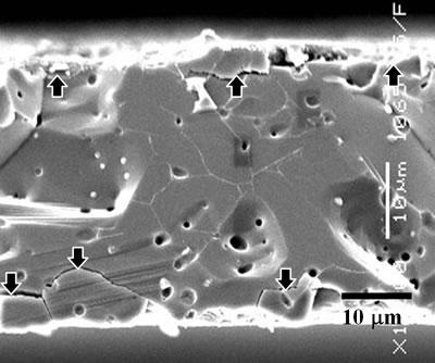
Figure 5 shows optical and SEM micrograph of the Al2O3 before and after grinding. We could grind Al2O3 from 1 mm thickness to 40 µm by only RFF grinding process in less than 50 min. The specimens ground by CSF system to 40 µm thickness broken in pieces due to defects generated by machining.
|
|
|
Figure 5. Photographs of the Al2O3 before and after grinding tests. (a) Optical photograph before and after grinding, (b) SEM photograph of a section view of ground Al2O3 (↑: machining defects).
|
Discussion
Measured parameters allow calculating the energy required to remove a unit volume of specimen, i.e., specific grinding energy, E. The specific grinding
energy was calculated by the ratio of the product of measured tangential grinding force and wheel speed, Vs, to the volumetric removal rate, Rv as [26];
 (2) (2)
Figure 6 shows the relationship between specific grinding energy versus feeding depth. The values of E represent the energy required to remove a given volume of materials as a characteristic parameter for each material. Each material should have a unique E value. Figure 6 shows high values of E for small amount of feeding depths. At null feeding depth, the grinding wheel barely touches the specimen, i.e., Rv is almost zero, but due to friction between the wheel and the specimen with addition of cooling water Ft is not null. In case of small feeding depth, required force for removal of the materials surface is relatively small compared with the friction between the wheel and specimen. The reason of the decrease between 0 and 10 of feeding depths is an artefact. During those feeding depths, the specimens are not really machined. For a larger feeding depth than 10 µm, Ft for real grinding force increases enough to allow to neglect the frictions. The values of E for the RFF method reach a constant value of about 17 GJ/m3 for the feeding depth larger than 10 µm.
|
|
|
Figure 6. The influence of the various feeding depths on the specific grinding energy, E of the CSF and the RFF. The value of E for the CSF has a minimum, but that for the RFF became stable as feeding depth increases.
|
However, those for the CSF method increase as the feeding depth increases above 10 µm. For the CSF system, the values of E show a minimum at the feeding depth of about 10 µm. The reason of the increase of E beyond 10 µm of feeding depth is due to the excess energy input to specimen, i.e., generating defects, sounds, vibration. In the case of the RFF system, for larger feeding depth, the table-feeding speed decreases and the grinding force increases. The values of E for the RFF method becomes a constant value, because the RFF method removes layers of materials at an amount characteristic to the energy of material by balancing automatically the table-feeding speed. It means that the table-feeding speed of the RFF system altered depending on grinding conditions, reducing or limiting excessive force on ground surface. However, the CSF system has a constant table-feeding speed. Therefore grinding forces increase as feeding depths increase, and excessive forces are created for a conventional CSF system. These results demonstrate that the RFF system can grind Al2O3 by constant E on any feeding depth.
Figure 7 shows the Weibull plot of ground Al2O3 fracture strength by different grinding systems. This graph shows the distribution of fracture strength for Al2O3 ground by feeding depths of 1 µm and 30 µm. Values of m obtained are called Weibull modulus. The large m results in small scattering of fracture strength. Using the probability and the fractured strength, size of machining damages can be evaluated. In Weibull statistics, it is assumed that fractures are caused by the weakest part in materials. Surface damages influence directly fracture strengths for a brittle material like Al2O3 ceramics. If there are no intrinsic defects and machining defects are the only possible defects, fracture strengths show machining defects size.
|
|
|
Figure 7. Probability of fractured strength for ground Al2O3 at 1 and 30 µm feeding depth for the CSF and the RFF system. The probability of fracture of the CSF machining shows the steep slope and low strength value. However, the RFF machining slope shows the moderate slope, widely distributed range of fracture strength, and higher strength than the CSF machining.
|
A conventional CSF surface machining process introduces damage into ground surface layers of ceramic materials. Uematsu et al. observed the size of machining damage reached from several tens of micrometers to several hundreds of micrometers [15, 16]. Those conventional grinding method, i.e., CSF grinding method, has a constant table-feeding speed independently from machining conditions or grinding wheel conditions. Therefore, excessive force occurred as increase feeding depth even if the grinding wheels have the same conditions. If an excessive force works on the machining surface during grinding, surface damages increase. Figures 8 (a) and (b) show schematically defects generated by excessive forces during machining, i.e., CSF case and defects by non-excessive forces during machining i.e., RFF method, respectively. These damages decrease the fracture strength for the case of Figure 8 (a).
|
|
|
Figure 8. The schematic of surface damage during different grinding method. (a) the CSF grinding method, (b) the RFF grinding method. ( ; machining defects, ; machining defects,  ; intrinsic defects - pore, impurities).. ; intrinsic defects - pore, impurities)..
|
The slopes of curves in Figure 7, m, represent the distribution of defects size to reduce fractured strength. The value of m is higher for the CSF process than that for the RFF process. The fractured strengths for the RFF process is higher than those for the CSF process. This high value of m means main fracture occurred by a similar size of defects. Considering these facts the defects created by the CSF process are larger than intrinsic defects as seen Figure 8 (a), and control the fractured strength. However, the RFF grinding method controls automatically table-feeding speeds as grinding conditions vary. The table-feeding speed is decreased to maintain the value of E constant automatically. Excessive forces on ground surface are reduced. The RFF process generated smaller defects than intrinsic defects, as seen in Figure 8 (b), to have smaller value of m and higher fracture strength. The cause of fractures of the RFF machined samples are coming from intrinsic defects with various different defect sizes.
Conclusions
In this study, the RFF grinding system was evaluated by examining fracture strength for ground Al2O3. Grinding forces of Al2O3 showed different tendency of grinding force increment as feeding depths increase for the CSF grinding tests and the RFF grinding tests. The different tendency in grinding forces was caused by the relative difference of table feeding behavior for both grinding systems. The grinding force for the RFF system indicates a lower value than that for the CSF system even for the same feeding depth. The grinding wheel wear for the CSF system increased rapidly as the feeding depth increased. The cause of low grinding wheel wears for the RFF system is attributed to automatically controlled table-feeding speeds depending upon the grinding conditions. For this reason, the CSF grinding method generated higher grinding forces than the RFF grinding method as feeding depth increased and suffered higher grinding wheel wear.
The maximum surface roughness did not change for any feeding depths. Specific grinding energy, E, depends on tangential force and removal rate of ground material. The values of E represent the energy required to remove a given volume of materials as a characteristic parameter for each material. The values of E for RFF method reach a constant value of about 17 GJ/m3 for the feeding depth larger than 10 µm. However, those for CSF method increase as the feeding depth increases above 10 µm.
Fractured strength does not change for any feeding depths on RFF grinding test, but, that for CSF grinding test decreased continuously as increased feeding depths. Probability of fracture of RFF machining shows a moderate slope, widely distributed range of fracture strength, and higher strength value than CSF machining. From the probability of fracture of the CSF and the RFF machining, the cause of main fracture for the RFF machining is machining defects, but that for the RFF machining is not only machining defects but also intrinsic defects before machining. These results show the table-feeing speed altered depending on grinding conditions and excessive force on ground surface. The grinding wheel conditions can be monitored easily by the table-feeding speed for the RFF system. Finally, we could grind the sintered-Al2O3 from 1 mm thickness to 40 µm in less than 50 min. The RFF grinding system can reduce machining defects of ground surface.
Acknowledgement
The authors wish to express their gratitude to the Japanese government for partially supporting this work through the 21st Century Center of Excellency (COE) Program of the Ministry of Education, Culture, Sports, Science and Technology.
References
1. S. W. Freiman, ‘‘Brittle Fracture Behavior of Ceramics’’, Am. Ceram. Soc. Bull., 67 (1988) 392-402.
2. Y. Shen, C.B. Luo, W.M. Zeng, X.P. Xu and Y.S. Gao, “Ceramics Grinding under the Condition of Constant Pressure” J. of Mater. Proc. Tech., 129 (2002) 176-181.
3. I. Shigematsu, K. Kanayama, A. Tsuge and M. Nakamura, “Analysis of Constituents Generated with Laser Machining of Si3N4 and SiC”, J. Mater. Sci. Lett., 17 (1998) 737.
4. K. Jodan, H. Funakoshi, K. Natsumaru and K. Ishizaki, “Laser dressing process of porous cast-iron bonded diamond grinding wheels for machining ceramics”, Adv. in Tech. of Mat. and Mat. Proc. J., 2 [2] (2000) 117-123.
5. J. K. Guha, “High-pressure waterjet cutting: An introduction”, Am. Ceram. Soc. Bull., 69 [6] (1990) 1027-1029.
6. L. Kahlman, S. Karlsson, R. Carlsson and C. G.Nilsson, “Wear and machining of engineering ceramics by abrasive waterjet”, Am. Ceram. Soc. Bull., 72 [8] (1993) 93-98.
7. L. M. Sheppard, “The challenges of ceramic machining continue”, Am. Ceram. Soc. Bull., 71 [11] (1992) 1590-1610.
8. S. Malkin and J. E. Ritter, “Grinding Mechanism and Strength Degradation for Ceramics”, ASME, J. of Engineering for Industry, 111 (1989) 167-173.
9. S. Malkin and T. W. Hwang, “Grinding Mechanism for Ceramics”, Annals of the CIRP(Conf. Int. pour la Res. de Prod.), 45 (2) (1996) 569-580.
10. D. Johnson-Walls, A. G. Evans, D. B. Marshall and M. R. James, “Residual Stress in Machined Ceramics Surfaces” J. Am. Ceram. Soc., 69 [1] (1986) 44-49.
11. H. P. Kirchner and E. D. Issacson, “Residual Stress in Hot Pressed Si3N4 Grooved by Single-Point Grinding”, J. Am. Ceram. Soc., 65 [1] (1982) 55-60.
12. B. G. Koepke and R. J. Stokes, “A study of grinding damage in Magnesium Oxide single crystals”, J. Mat. Sci., 5 (1970) 240.
13. K. A. Kibble and L. A. Phelps, “Influence of grinding parameters on strength of reaction-bonded silicon carbide”, Br. Cearm. Trans., 94 [5] (1995) 209-216.
14. M. Hakulinen, “Residual strength of ground hot isostatically pressed silicon nitride”, J. Mater. Sci., 20 (1985) 1049-1060.
15. W. Kanematsu, M. Sando, L. K. Ives, R. Marinenko and G. D. Quinn, “Dye Impregnation Method for Revealing Machining Crack Geometry”, J. Am. Ceram. Soc., 84 [4] (2001) 795-800.
16. K. Sato, S. Yonetani, S. Tanaka, N. Uchida and K. Uematsu, “Relationship between microstructure and machining damage of alumina ceramics”, 15th Fall Meeting of The Ceramic Society of Japan (Akita, Japan, 2002), 3D20, p.215.
17. T. Fukami, H. Masumura, K. Suzuki and H. Kudo, “Method of Manufacturing Semiconductor Mirror Wafers”, European Patent Application, EP0782179A2, Bulletin, 27 (1997).
18. M. Liu, J. I. Takagi and A. Tsukuda, “Strength recovery of ground ceramics via electric furnace heating”, J. of Mater. Proc. Tech., 127 (2002) 107-114.
19. T. Shirakashi, W. Gong and T. Obikawa, “In-process Monitoring of Tool Damage by Active Method – Behavior of Damping Ratio with Tool Wear Development”, J. of the Japan Soc. for Precision Engineering, 61 [12] (1995) 1750-1754.
20. M. E. R. Bonifacio and A. E. Diniz, “Correlating Tool Wear, Tool Life, Surface Roughness and Tool Vibration in Finish Turning with Coated Carbide”, Wear, 173 [1-2] (1994) 137-144.
21. J.H. Ahn, H.S. Lim, S. Takata and T. Sata, “Machining Process/Tool Wear Monitoring System Based on Real-Time Sound Recognition”, J. of Japan Soc. for Precision Engineering, 60 [8] (1994) 1144-1148.
22. C. R. Heiple, S. H. Carpenter, D. L. Armentrout and A. P. McManigle, “Acoustic Emission from Single Point Machining-Source Mechanisms and Signal Changes with Tool Wear”, Materials Evaluation, 52 [2] (1993) 269-274.
23. H. Takeshita and I. Inasaki, “Monitoring of Milling Process with an Acoustic Emission Sensor”, J. of Japan Soc. for Precision Engineering, 59 [2] (1993) 269-274.
24. A. E. Diniz, J. J. Liu and D. A. Dornfield, “Correlating Tool Life, Tool, Wear and Surface Roughness by Monitoring Acoustic Emission in Finishing Turning”, Wear, 152 (1992) 395-407.
25. H. J. Kim, K. Matsumaru, A. Takata and K. Ishizaki, “Grinding Behavior of Silicon Wafer and Sintered Al2O3 by Constant-Force-Feeding Grinding System”, Adv. in Tech. of Mat. and Mat. Proc., J. 5 [2] (2003) 50-53.
26. A. Takata, Doctoral Dissertation of Nagaoka University of Technology, Japan (in Japanese) (1998).
Contact Details
|