Sponsored by AdmesyMay 20 2015
The procedure of taking reflective measurements using probes is discussed in this article. The standard principles of 0º and 45º probes for reflective measurements are explained, and some advice is given to help ensure that precise measurement results are obtained.
Image Credit: wacomka/Shutterstock.com
Reflective Probes
A number of applications require reflective measurements. In certain cases, it may be possible to determine a large spot directly with a 45/0 geometry, such as when measuring the color of plastic, wood or paper.
However, in certain cases, measurement of a large spot or direct measurement of a sample with a device is not possible. This may be the case in situations where the temperature of the sample is outside of the acceptable range of the device.
The sample spot to be measured may be too small for direct measurement using a reflective measurement device. It is not always possible in production environments to directly access the sample because of the way that the production lines are setup. Further, when measuring liquids, direct contact with the measurement device should often be avoided to prevent damage to the equipment.
Reflective probes can prove to be a solution in these situations. The head of the reflective probe can concentrate remote measurement and illumination onto a small spot. The head of the reflective probes offered by Admesy comprises seven fibers.
Six fibers are positioned equally around a circle, where they illuminate the center fiber. The reflected light is led back by the center fiber towards a measurement device, such as a colorimeter or a spectrometer. All seven fibers are located within a circular shape, enabling reflective measurements with a 1 mm spot diameter.
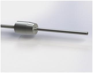
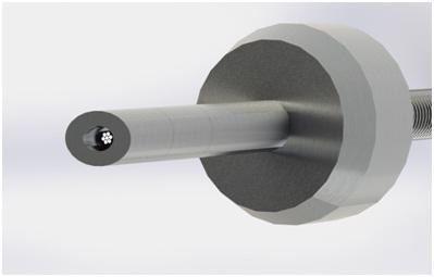
Figure 1. Reflective probes. Detail picture on the right shows the seven fibers. Center fiber is connected to measurement device, the six outer fibers are connected to a light source. Image Credit: Admesy
Reflective probes benefit from very precise, located measurements, as well as a flexible measurement system, where either a colorimeter or a spectrometer may be used depending on the application. The type of light source to be used, LEDS or halogen, can also be selected based on the type of material to be measured. The measurement procedure is essentially the same for any reflective probe setup.
Types of Reflective Probes
A straight (or 0°) probe is used in measurements wherein the specular component must be included, and a 45º probe is used when the specular component must be excluded.
The differences between both reflective probe types is shown in Figure 2. If conducting measurements with the straight probe, reflections of high gloss materials will be included in the measurement results, causing high gloss samples to appear brighter and less saturated when compared to matte samples of the same color.
Hence, the straight probe is suitable for measurements which should include the specular component. The 45º probe is suited to cases where gloss needs to be excluded from the measurement. Light that strikes the surface at an angle of 45º will reflect at an equal but opposite angle.
Since the measurement fiber is not located in that direction, the light reflected at equal but opposite angles will not be measured. Only diffuse reflected light that shows the sample’s actual color is measured.
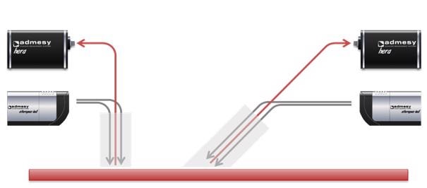
Figure 2. Principle of 0º reflective probe setup (left) and 45º probe (right). Image Credit: Admesy
Reflective Measurement Procedure with Reflective Probes
This section describes the measurement procedure using an Admesy Steropes LED light source and a HERA spectrometer linked to a straight probe. This setup helps to determine the sample’s spectral distribution while including the specular component.
The first step in this procedure involves the use of a white tile to take a reference measurement. This step is vital in order to ensure that data is repeatable and usable before commencing the actual measurement. Should the measurement data need to be compared with data from other setups, it is essential that a calibrated white tile is used. The measured sample color may be affected by eventual differences in white tiles.
Depending on the application, the probe can either be mounted in a holder or held by hand above the sample being analyzed. For repeated measurements, such as in a production line where repeatability is key, a holder is ideal. In laboratory settings where just few samples are measured or measurement is conducted at different spots, it might be more appropriate to hold the device.
Both stages of the measurement procedure are shown in Figure 3.
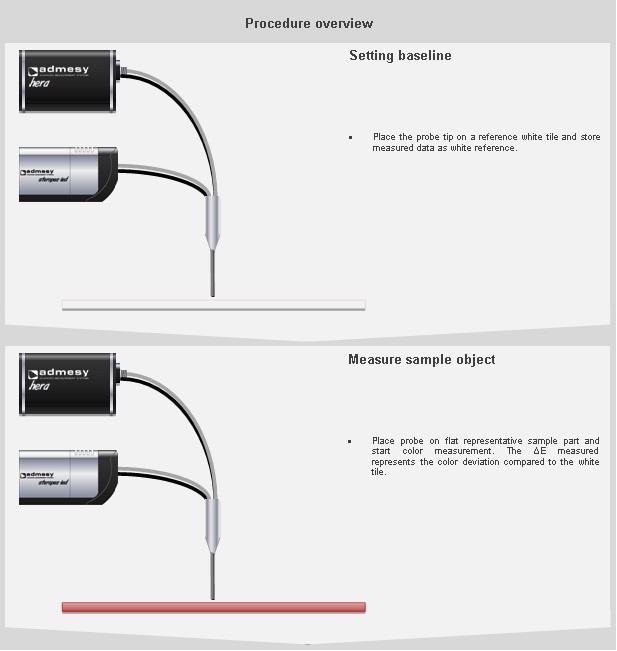
Figure 3. Reflective measurement procedure with reflective probes. Image Credit: Admesy
General Tips for Reflective Measurements with Probes
In order to make sure that reflective measurements will provide precise and usable data, the following guidance should be followed. These tips will ensure repeatability and stable measurements.
- The angle and alignment of the probe and sample spot to be measured need to be controlled. Both straight and 45° probes should be used at the angle they are intended for. While altering the angle, changes in measured data may take place, which could affect the repeatability and usability of data.
- Check that the appropriate fibers are being used. It is important to properly connect measurement and illumination fibers. The outer fibers should connect to the light source, and the inner fiber to the measurement device.
- The minimum radius of fibers must be checked, and fibers should not be bent. Should the fibers be bent at too sharp an angle, the may break, and illumination may be affected, or light may be blocked before entering the measurement device, resulting in no data being taken.
- The ambient light level must be controlled at the location of measurement. If the reflective probe is held above the sample, it is possible that ambient light may enter the reflective probe and impact the measured data.
- The reference white tile should be controlled prior to performing the baseline measurement. If the reference white tile has not been calibrated, it is not possible to compare measured data to reference results, potentially resulting in a false deltaE.
- Choose a representative sample to be measured.
- While conducting a reflective measurement, consider the spectral response of the light source in comparison to the sample being analyzed. The spectral response of the light source must match the application. If a red sample is measured with a blue LED light source, it is not possible to obtain usable data.
- Consider the impact of luminescent objects while conducting a reflective measurement.

This information has been sourced, reviewed and adapted from materials provided by Admesy.
For more information on this source, please visit Admesy.