Throughout the process of steel production, steel plants monitor the decline in carbon levels. At the beginning of the procedure, raw iron has a carbon content of up to 4-5% while the stainless-steel end product has just a few ppm. As well as affecting texture, the carbon content influences the physical properties of iron, for example its hardness, elasticity and levels of magnetism.
This can be illustrated by the following examples: cast iron (2-4% C) is inelastic but castable; tool steel (0.4-1,7% C) is elastic and malleable, carbon steel (<0.4% C) is forgeable and suitable for use in sheets, tubes and steel girders (1). Within an iron matrix, carbon can be detected in different forms, either bound to other elements as carbide, solved in the iron matrix or as elemental carbon (2). Carbon and sulfur concentrations are detailed in the cross-reference book, Key to Steel, due to their influence on physical properties.
Measurement of Carbon and Sulfur Concentrations
It is for the above reasons that it is vital to identify carbon and sulfur levels with both speed and accuracy. A variety of techniques can be used to determine these concentrations, including multi-element methods such as spectrometry or specialized carbon/sulfur analysis, and these can be applied to steel, iron-based products or common foundry products, such as ferro chromium.
Methods such as spark OES or GDOES (also known as multi-element techniques) work by extracting a small area of the surface and stimulating the displaced atoms. This stimulation leads to element-specific optical emission, the effects of which can be measured through an optical system such as a Rowland circle with CCD detection.
The wavelengths produced by these atoms depend on their chemical make-up and will vary between elements. It is therefore possible to measure not only carbon and sulfur simultaneously, but also other elementslike manganese or chromium.
To achieve a reliable and unambigious measurement, it is necessary to have a flat, uncontaminated sample surface. Using the aforementioned multi-element techniques to analyze items such as wires, granulates, powders or samples which contain elemental contamination of carbon or sulfur is unlikely to provide successful results (3).
Alternative spectrometric processes such as ICP OES can be applied to a variety of sample shapes but they do need a dissolved sample. The blank values of the acids and solvents used to achieve this dissolution must be accounted for, especially in materials such as stainless steel, where the carbon and sulfur concentration to be examined is at a very low level.
An alternative principle of measurement is provided by carbon/sulfur (or combustion) analyzers. Here, an induction furnace is used to melt a sample and a high flow of oxygen (e.g. 180 l/h) is introduced. This causes the bound carbon and sulfur to combust to carbon dioxide and sulfur dioxide, which can subsequently be analyzed with electronic detectors such as infrared cells or thermal conductivity cells.
Prior to the development of electronic detectors capable of simultaneous carbon and sulfur measurement, the most common methods available for such tests took up to 90 minutes to examine a single element (2). To achieve this, samples were exposed to heat in a resistance furnace (1,200 °C for carbon and 1,400 °C for sulfur), before the released gases were measured using techniques such as gravimetry, gas volume measurement, coulometry, conductometry or alkali titration (2). Because of the number of steps which needed to be undertaken manually, as well as the comparatively low furnace temperatures, these methods were susceptible to error.
Modern Combustion Analyzers
Unlike these outdated techniques, modern combustion analyzers measure carbon and sulfur concentrations in a matter of seconds. Products such as ELTRA’s ELEMENTRAC CS-i require an average analysis time of just 40 seconds to quantify concentrations of both carbon and sulfur.
The CS-i makes use of a power-controllable induction furnace with intelligent lance management, a heated dust trap, an integrated catalyst and up to four infrared cells, offering a broad measuring range. This system provides quick and reliable elemental analysis which is compliant with all relevant international standards and literature. Carbon and sulfur levels can be measured from a few ppm up to the percentage range, and the equipment is operated by expert and non-expert staff alike.
Only a small number of manual steps is required for analysis, including weighing of the sample in a ceramic crucible, logging it into the software, adding an accelerator, and beginning the measuring process. From here, no further user involvement is required, with the remainder of the process managed by the software and hardware of the analyzer. The following paragraphs offer further explanation of the ‘black box combustion analyzer’ and its processes.
Table 1. Standards for carbon and sulfur analysis with combustion analyzer
| Standard |
Released |
Title |
| ASTM E 1941 |
2010; reapproved 2016 |
Standard Test Method for Determination of Carbon in Refractory and Reactive Metals and their Alloys by Combustion Analysis |
| ASTM E 1019 |
2011 |
Standard Test Methods for Determination of Carbon, Sulfur, Nitrogen, and Oxygen in Steel, Iron, Nickel, and Cobalt Alloys by Various Combustion and Fusion Techniques |
| DIN 24935 |
1992 |
Determination of sulfur content of steel and iron by infrared absorption spectroscopy after combustion in an induction furnace |
| DIN EN ISO 9556 |
2002 |
Steel and iron - Determination of total carbon content - Infrared absorption method after combustion in an induction furnace |
| DIN EN ISO 15349-2 |
2003 |
Unalloyed steel - Determination of low carbon content - Part 2: Infrared absorption method after combustion in an induction furnace (with preheating) |
| DIN EN ISO 15350 |
2010 |
Steel and iron - Determination of total carbon and sulfur content - Infrared absorption method after combustion in an induction furnace (routine method) |
| ISO 13902 |
1997 |
Steel and iron - Determination of high sulfur content - Infrared absorption method after combustion in an induction furnace |
A) Sample Preparation
A variety of processes is used to prepare a sample for combustion analysis, including preparing a sample from a liquid melt, reducing the size of a larger sample such as an iron bar, or cleaning a sample, for example by cleansing with acetone, immediately prior to analysis. The sample preparation process from liquid iron or steel is described in DIN EN ISO 14284:2002 or the similar standard ASTM E1806.
How you prepare a sample from a melt is dependent on the preferred sampling tools as well as the iron base to be measured, e.g. pig iron, cast iron or steel. Using probes, or sampling with spoons before cooling the sample in a mold are both accepted methods.
Some mold configurations produce a sample for spectrometric analysis and some supplementary pins for elemental analysis (Figure 2 in the ASTM E 1806-09 standard). Molds such as this need only be created once and can subsequently be re-used as needed. Where pins are inaccessible from the mold, a sample for C/S analysis may be obtained by penetrating a larger solid sample. The necessary speed of drilling, along with additional details, can be found in the previously noted ASTM and ISO standard.
When analyzing iron samples, no cleaning or other sample preparation is generally required before the process. It is, however, vital that samples of pig iron, or those acquired during the manufacture of cast iron, are not treated with any organic solvents, including acetone, as this could affect the dispersion of graphite and iron (ASTM E 1806), distorting the measured carbon levels.
For other matrices, including refractories, it is necessary to include a cleaning step prior to measuring carbon and sulfur concentrations using a combustion analyzer. The ASTM E 1941 suggests removing impurities from the surface using acetone or another organic solvent.
B) The Combustion Process
Following the preparation of a sample sized around 500-1,000 mg, this is placed in a ceramic crucible and a suitable accelerator is added. To guarantee smooth combustion and total release of the bound carbon and sulfur in an induction furnace, it is necessary to use metallic accelerators such as copper, tungsten, or a combination of tungsten and tin.
To begin the combustion procedure, the ceramic crucible containing the sample and accelerator is placed in the induction coil, and the furnace is started. The coil generates an electric field which interacts with the accelerator’s free electrons and as a result, the mixture is heated to a melting point of up to 2,100 °C.
The actual temperature in the crucible is higher than 2,100 °C, due to the powerful stream of oxygen (e.g. 180 l/h) in the combustion area and the oxidizing reaction of the sample and accelerator. The temperature produced is hot enough to melt and oxidize even such refractories as molybdenum, which has a melting point of 2,623 °C.
Table 2. Overview of accelerators, calibration materials and sample weights
| Standard |
Measured elements |
Recommendation |
| ASTM E 1941 |
Carbon |
Calibration material: CRM
Recommended sample weight: NN
Accelerators: iron plus copper or other (tungsten / tin) |
| ASTM E 1019 |
Carbon, Sulfur |
Calibration material: CRM for carbon; K2SO4 for sulfur
Recommended sample weight: 1000 mg
Accelerator: copper (for carbon), tungsten (for sulfur) |
| DIN 24935 |
Sulfur |
Calibration material: K2SO4
Recommended sample weight 500 mg or 1000 mg
Accelerator: tungsten |
| DIN EN ISO 9556 |
Carbon |
Calibration material: BaCO3; Na2CO3; sucrose
Recommended sample weight: 500 mg or 1000 mg
Accelerator: copper, tungsten, tungsten/tin |
| DIN EN ISO 15349-2 |
Carbon |
Calibration material: sucrose, CaCO3
Recommend sample weight: 1000 mg
Accelerator: copper; tungsten/tin |
| DIN EN ISO 15350 |
Carbon and Sulfur |
Calibration material CRM
Recommended sample weight: NN
Accelerators: copper or tungsten or tungsten / tin |
| ISO 13902 |
Sulfur |
Calibration material BaSO4
Recommended sample weight: 500 mg
Accelerator: tungsten plus pure iron |
Unlike a resistance furnace, an induction furnace cannot be set to a consistent temperature, for example, 2,000 °C. The chemical composition of the materials in the crucible, the quantities of both accelerator and sample and the intensity of the oxidizing process all have an effect on the temperature reached inside the crucible. However, the combustion temperature can also be affected by decreasing the power applied by the induction furnace.
To achieve this, the ELEMENTRAC CS-i utilizes a phase angle controller. Additionally, low melting samples such as copper or magnesia are measured more accurately at lower temperatures. This improved accuracy is reached mainly by reducing the sputtering within the crucible. Sputtered samples generally condense in the combustion tube, leaving the bound carbon and sulfur inaccessible.
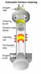
Figure 1. ELEMENTRAC CS-i Induction Furnace
As well as a suitable accelerator, an appropriate level of oxygen supply is required to ensure total combustion in a carbon/sulfur analyzer. The intelligent lance management (ILM) of the ELEMENTRAC CS-i provides effective control of the oxygen supply throughout the combustion procedure.
For solid metallic samples such as steel, a high oxygen flow (180 l/h) is supported via a lance which directs the oxygen stream straight onto the sample and ensures total combustion. Dusty samples such as fine powdered ceramics or sands could be blown out of the crucible as the oxygen stream is directed at them. To avoid this, the oxygen is provided by a second supply which solely flushes the chamber. Further into the process (e.g., after 20 seconds), the intelligent lance management switches on the oxygen lance to ensure complete combustion.
C) Heated Dust Trap and Dust Management
Combustion of metallic samples creates a fine-grained dust which may affect measurement of carbon and sulfur in infrared cells. To avoid any build-ups of dust within the analyzer, there is a small, meshed metallic filter placed straight behind the induction furnace within the ELEMENTRAC CS-i.
This filter - arranged in a heated housing - prevents any condensation of water traces which could cause artificially low measurements of sulfur concentrations. Traces of water vapor are present in the combustion gas mostly due to the moisture of the sample as well as, to some degree, the oxidized hydrogen bound in the sample.
Without a heated dust trap, the water vapor would condense in the metallic filter and take in the gaseous sulfur dioxide, leaving the formed sulfuric acid unavailable for determination in the infrared cells. The heated dust trap of the CS-i thus ensures the complete transfer of both water vapor and gaseous sulfur dioxide into an anhydrone tube. This anhydrone tube extracts the water vapor entirely, without any adverse impact on the sulfur dioxide and its measurement in the infrared cells.
D) Catalyst
Carbon dioxide and sulfur dioxide are the fundamental reaction products created in the combustion process. A miniscule quantity of carbon monoxide is also created in each induction furnace. However, this would be undetectable in standard carbon dioxide infrared cells, and unless a further oxidizing process was undertaken, the measurement of carbon would display lower results than anticipated.
To modify carbon monoxide into carbon dioxide, a variety of chemicals or catalytic active substances such as copper oxide or platinum can be used. The ELEMENTRAC CS-i makes use of a platinum-based catalyst with silica as carrier material. This option is cost-friendly as it ensures safe and predictable oxidization. Maximum safety levels for determination of carbon with the CS-i are ensured through use of an increased catalyst length with temperature control.
E) Detection
Infrared or thermal conductivity cells are state-of-the-art electronic detectors for combustion analyzers. However, those which use thermal conductivity cells, as outlined in the ASTM E 1019-11, are limited to determination of carbon alone, while the ELEMENTRAC CS-i with its up to four infrared cells, guarantees safe and effective determination of both carbon and sulfur at the same time.
Unlike thermal conductivity cells, the IR cells are element selective. This means that the determination of elements such as sulfur is not affected by the presence of large quantities of carbon dioxide. Instead, infrared cells use the specific wavelength absorption of the carbon dioxide and/or sulfur dioxide molecule, which means that chemical bonding in these molecules starts to swing when IR radiation of the complementary wavelength is applied.
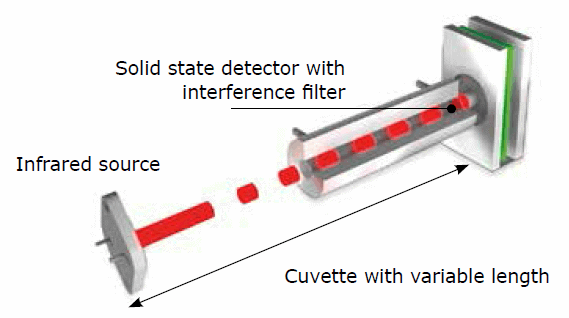
Figure 2. Infrared cells with flexible measuring range
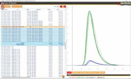
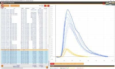
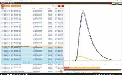
The emitter and detector give out a continuous electrical signal prior to combustion gases passing the IR cell. As the combustion gas enters, the detector is exposed only to areduced amount of light due to the interaction between the emitted light and the carbon dioxide or sulfur dioxide molecules.
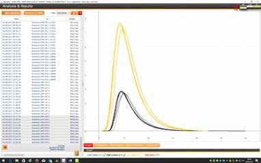
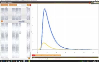
The subsequent variation of the electrical voltage of the detector is shown as a peak and can be used for mathematical integration. Examples of some prototypical peaks for varying matrices can be found in the measuring data of the CS-i in the appendix. To suit user needs, adjustable IR cells with different sensitivities are available for the CS-I.
A short IR path length equates to a short reaction path of IR light and combustion gas, making such a cell ideal for high element concentration. Conversely, expanding the IR path length also increases the reaction path of light and gas molecule, making the IR cell more sensitive for low element concentrations.
Despite the robustness of infrared cells as a detection system, they are still susceptible to damage from gaseous halogens such as fluorine or chlorine, which can be found in samples such as ores, salts or acidified matrices. To prevent damage of the IR cell, the use of both a halogen trap, and a golden IR path for increased chemical resistance are advised. These are available as optional extras with the ELEMENTRAC CS-i.
F) Calibration
Unlike procedures using classic measurement methods such as gravimetry, combustion analyzers such as the ELEMENTRAC CS-i, need to have a calibration process for determining accurate element concentrations. As with spectrometric techniques and other methods of relative measurement, combustion analysis requires that the peak zone of a carbon or sulfur measurement corresponds with an element concentration.
As the inductive combustion of samples ensures the total release of the bound carbon and sulfur, C/S analyzers are able to be calibrated with certified reference materials (CRM) or with primary substances like CaCO3 or BaSO4 (Table 2). While the use of CRM is considered standard practice, the use of primary substances offers greater safety for samples analyzed in a round robin test.
G) Conclusion
Using the ELEMENTRAC CS-i to measure carbon and sulfur concentrations is fast and simple, requiring the user to merely weigh the sample, apply an accelerator and log the data in the software. With just these basic steps, accurate and reliable carbon and sulfur measurements can be achieved for a variety of samples and matrices. This is further demonstrated in the below measuring data.
References and Further Reading
- HollemannWiberg, Inorganic Chemistry, 33nd edition, 1993, p 1133ff
- Handbuchfür das Eisenhüttenlaboratorium; 2nd edition, 2013; Part (1) classic method ; Volume (2): Analysis of metals
- ASTM E 1806-09; page 13
- Handbuchfür das Eisenhüttenlaboratorium; 2nd edition, 1998; Part (2) new method ; Volume (2): Analysis of metals
- ASTM E 1941-10; page 2, Note 7
Measuring Data of the ELEMENTRAC CS-i
(1) Steel Samples
Steel samples can be measured with a sample weight of 500 or 1,000 mg and with 1.5g tungsten as accelerator:
Reference material: ECISS EURONORM - ZRM 079-2 Machining Steel (*)
(*) certified value:
C: 0.596 % ±0.006
S: 0.192 % ±0.006
Weight
[mg] |
Carbon
[%] |
Sulfur
[%] |
| 498.9 |
0.5981 |
0.1855 |
| 498.8 |
0.5997 |
0.1928 |
| 501.0 |
0.5930 |
0.1913 |
| 503.0 |
0.5974 |
0.1932 |
| 506.7 |
0.5922 |
0.1930 |
| 503.2 |
0.5984 |
0.1946 |
| 504.5 |
0.6002 |
0.1960 |
| 504.4 |
0.5991 |
0.1949 |
| 504.3 |
0.5902 |
0.1893 |
| 506.5 |
0.5955 |
0.1925 |
| Mean value |
0.5964 |
0.1923 |
Deviation / relative
deviation |
±0.0035 (0.6%) |
±0.0030 (1.6%) |
Reference material: Alpha Resources AR 875 (LOT 1216F) Steel rings (*)
(*) certified value:
C: 0.799% ±0.017
S: 0.0125% ±0.0034
Weight
[mg] |
Carbon
[%] |
Sulfur
[%] |
| 1003.4 |
0.8005 |
0.0128 |
| 1001.9 |
0.8003 |
0.0125 |
| 1002.6 |
0.8012 |
0.0126 |
| 1003.2 |
0.8007 |
0.0126 |
| 1001.8 |
0.7971 |
0.0125 |
| 1004.2 |
0.7952 |
0.0125 |
| 1003.6 |
0.7962 |
0.0124 |
| 1003.1 |
0.7976 |
0.0123 |
| 1003.2 |
0.8020 |
0.0124 |
| 1002.9 |
0.8024 |
0.0123 |
| Mean value |
0.7993 |
0.0125 |
Deviation / relative
deviation |
±0.0026 / 0.32% |
±0.0002 / 1.21% |
Reference material: EURONORM - CRM 281-1 Highly Alloyed Steel (*)
(*) certified value:
C: 0.048 % ±0.002
S: 0.016 % ±0.001
Weight
[mg] |
Carbon
[%] |
Sulfur
[%] |
| 501.8 |
0.0482 |
0.0163 |
| 501.4 |
0.0479 |
0.0162 |
| 503.0 |
0.0479 |
0.0161 |
| 506.4 |
0.0481 |
0.0161 |
| 505.6 |
0.0481 |
0.0160 |
| 498.5 |
0.0482 |
0.0160 |
| 498.8 |
0.0477 |
0.0158 |
| 497.5 |
0.0479 |
0.0158 |
| 501.5 |
0.0479 |
0.0158 |
| 499.6 |
0.0479 |
0.0161 |
| Mean value |
0.0480 |
0.0160 |
Deviation / relative
deviation |
±0.0002 / 0.4% |
±0.0002 / 1.1% |
(2) Cast Iron
Steel samples can be measured with a sample weight of 500 mg and with 1.5 g tungsten and 0.7 g high purity iron as accelerator:
Reference material: ELTRA cast iron 92400-3100 (LOT1014C) (*)
(*) certified value:
C: 4.20% ±0.06 (1.42%)
S: 0.023% ±0.002 (8.69%)
Weight
[mg] |
Carbon
[%] |
Sulfur
[%] |
| 512.2 |
4.19 |
0.024 |
| 501.1 |
4.19 |
0.024 |
| 509.5 |
4.20 |
0.022 |
| 507.0 |
4.21 |
0.023 |
| 505.1 |
4.21 |
0.023 |
| 500.8 |
4.19 |
0.022 |
| 518.1 |
4.20 |
0.022 |
| 500.0 |
4.20 |
0.022 |
| 502.2 |
4.19 |
0.022 |
| 500.5 |
4.21 |
0.022 |
| Mean value |
4.20 |
0.023 |
Deviation / relative
deviation |
±0.01 / 0.2% |
±0.001 / 3.54% |
(3) Pure Iron
Pure iron samples can be measured with a sample weight of 500 or 1,000 mg and with 1.5 g tungsten as accelerator. For optimum accuracy, the use of a carrier gas purification furnace is recommended.
Reference material: ELTRA 88600-0013 (LOT 716C) (*)
(*) certified value:
C: 6 ppm ±4 ppm
S: 11 ppm ±4 ppm
Weight
[mg] |
Carbon
[%] |
Sulfur
[%] |
| 504.6 |
5.48 |
11.27 |
| 499.6 |
5.86 |
11.18 |
| 504.7 |
6.39 |
11.84 |
| 497.9 |
5.86 |
11.42 |
| 498.6 |
5.87 |
10.49 |
| 503.9 |
6.95 |
11.92 |
| 503.3 |
6.46 |
11.17 |
| 498.3 |
5.84 |
10.68 |
| 507.2 |
6.41 |
11.75 |
| 498.6 |
5.64 |
11.29 |
| Mean value |
6.08 |
11.30 |
Deviation / relative
deviation |
±0.45 / 7.48% |
±0.47 / 4.14% |
(4) Ferro Chromium
Ferro Chromium samples can be measured with a sample weight of approx. 150 mg and with 1.5 g tungsten and 0.7 g of high purity iron as accelerator
Reference material: Euronorm 585-2 (*)
(*) certified value:
C. 5.488% ±0.02 (0.4%)
S: 0.032% ±0.0012 (3.75%)
Weight
[mg] |
Carbon
[%] |
Sulfur
[%] |
| 149.8 |
5.506 |
0.032 |
| 150.8 |
5.468 |
0.032 |
| 150.7 |
5.502 |
0.033 |
| 157.6 |
5.502 |
0.033 |
| 149.8 |
5.461 |
0.032 |
| 150.3 |
5.472 |
0.031 |
| 154 |
5.504 |
0.032 |
| 151.8 |
5.487 |
0.032 |
| 150.4 |
5.497 |
0.033 |
| 155.7 |
5.482 |
0.031 |
| Mean value |
5.488 |
0.032 |
Deviation / relative
deviation |
±0.017 / 0.30% |
±0.001 / 2.09% |
Technical Data
| |
ELEMENTRAC CS-i |
| Measuring range* |
For nominal sample weight of 1000 mg |
| 2-cell configuration |
Carbon: 2 ppm – 7 % / Sulfur: 2 ppm – 0.42 % |
| 4-cell configuration |
Carbon: 0.6 ppm – 3.5 % / Sulfur: 0.6 ppm- 2.3 % |
| Analysis time |
40 seconds (nominal) |
| Cycle time |
80 seconds |
| Measuring method |
Combustion via induction furnace followed by Infrared
detection for carbon dioxide (C) and sulfur dioxide (S) |
| Chemical reagent |
Magnesium perchlorate
Sodium hydroxide
Platinized silica
Cellulose |
| Gas requirements |
Oxygen 99.5 %; 2-4 bar (30-60 psi)
Compressed air: 4-6 bar (60 – 90 psi) |
| Gas consumption |
180 L/h (oxygen, during analysis) |
| Furnace |
Induction 2.2 kVA (power adjustable 0-100%) |
| Operation conditions |
15-35°; 20-80 % rel. humidity (not condensing) |
| Electrical power requirement |
230 VAC +-10 %; 50/60 Hz; 16 A fuse |
| Weight |
approx. 150 kg |
| Dimensions (W x H x D) |
520 x 840 x 750 mm |
| Required accessories |
PC, TFT, Balance |
| Options |
Carrier gas purification furnace
Autoloader (36 postions) |
* Depending on configuration; can be modified to other working ranges; limit of detection measured with gas dose analysis and blank measurement; different values are possible according to application selected.

This information has been sourced, reviewed and adapted from materials provided by ELTRA GmbH.
For more information on this source, please visit ELTRA GmbH.