Depending upon the distance between the surface of a capacitance probe and a target source, the electrical capacitance that is formed between these two objects will vary. In an effort to improve measurement problems that industrial researchers have always faced, parallel plate capacitance sensors have offered numerous advantages as compared to other sensing systems. Some of the specific advantages associated with capacitance sensors include:
- No physical contact between the sensor and target required
- Zero mechanical loading
- Prevention of any wear to the probe or target
- Prevention of any distortion on the target sample
- Improved stability, precision and resolution
- Ability to work in harsh environments
- Can withstand temperatures as high as 1200 ºF (650 ºC), and cryogenic temperatures as high as 4 ºK
- Can function well in extremely high magnetic fields of at least 2 Tesla and vacuum conditions of 10-7 Torr
- Costs approximately 30% less than typical laser interferometers at a matched or higher functionality
MIT Instruments offers novel digital capacitance technologies that, believe it or not, exceed the traditional measurement credentials of capacitance sensors. For example, MIT Instruments’ AccumeasureTM D Series amplifiers exhibit the following exceptional properties:
- 24-bit resolution
- Precision exceeds that of commonly used 16-bit A/D converters
- Less noisy as compared to traditional 16-bit A/D converters
- Reduced non-linearity errors as compared to traditional 16-bit A/D converters
- Eliminated drift problems through built-in digitally selectable filters that optimize resolution and frequency response without requiring an additional offset or drift to be added to the full sensor
- Extended digital range as compared to analog amplifiers
- Multiple range extensions (as high as 10) can be added at time of ordering
- Superior linearity and accuracy by digitally correcting linearity at every point in the range - this new feature is comparable to previous amplifiers that would only correct linearity at a few points on the displacement curve
- Linearity specifications of 0.01% full scale range are typical
- Compatible with the ‘Internet of Things’ with Ethernet and USB, allowing users to incorporate multiple sensors or web-based applications that can even be displayed on a smart phone.
The following applications address a wide range of industry sectors in which the capacitance sensors offered by MTI Instruments exceed in performance as compared to other measurement systems at a fraction of the cost.
Consumer Electronics: Rapid Motion Control at a Sub-Micron Accuracy
Today’s electronic manufacturing process requires the rapid and precise positioning of the many miniature components that comprise these devices. For many assembly lines, process control has shifted from a previously millimeter level of accuracy to a micron, or even sub-micron, levels.
To meet the demand of improved precision of these device components, these manufacturing facilities often require the piezoelectric positioning of actuators and/or voice coil motors that are equipped with a closed-loop feedback control.
Previously, the analog feedback obtained from capacitance sensors enabled the closed-loop control of conventional positioning stage and extreme positioning accuracies using voice coil motors or piezoelectric stages. While useful in theory, these systems often required motion stage feedback to be obtained from a position sensor, which was a severe limitation of analog systems.
Digital closed-loop control systems instead offer an improved stability without expelling the same noise, interference, and/or distortion that often occurred when using analog systems in the past.
The new generation of digital capacitance sensor systems, which are comprised of a digital capacitance probe and Accumeasure capacitance amplifier, allow users to achieve a closed-loop feedback that is ideal for precision positioning applications that involve either piezoelectric actuators or voice coil motors.
During the operation of these sensor systems, the digital probe is used to measure the piezo stage position in real time, whereas the digital Accumeasure amplifier will follow and send the stage position to the programmable motion controller through an Ethernet output.
Each novel digital capacitance sensor system is equipped with a motion controller that is used to compare feedback signals to a command position set point, thereby allowing the controller to adjust the piezo stage with sub-micron precision if necessary. If a change in the set point or disturbance in the process is detected, the controller then performs a series of calculations based on the changes to ultimately return the motion stage to the exact commanded position.
The overall performance of the capacitance sensor system varies depending on the response rate of the controller in conjunction with each of the positioning components and the feedback sensor. Some of the benefits specifically associated with a digital capacitance sensor for this application include:
- Built in superior 24-bit digital output: eliminates the use of a separate A/D system
- Accommodates commercial off-the-shelf closed-loop servo software
- Digitally adjustable filter allows for the highest loop response and overall resolution
- Very low linearity error ensuring that the highest precision of the system in absolute positioning
- Multiple probes can be networked without any signal degradation occurring
- Ethernet output for remote locations of sensors
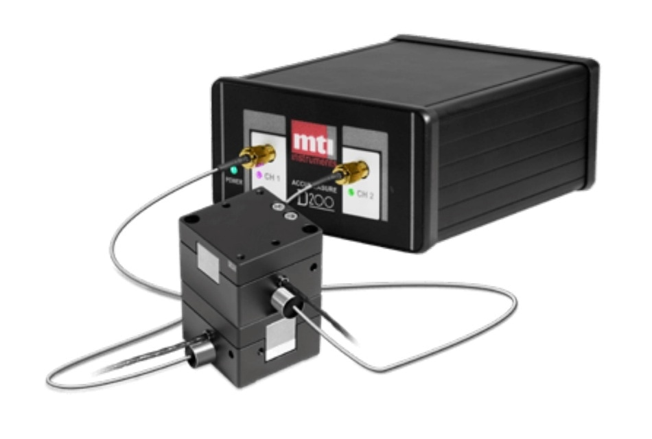
MTI digital capacitance amplifier with MTI ASP-500M- ILA capacitance probe, embedded in the Piezo System Jena PX-100 stage. The digital amplifier offers exceptional accuracy and linearity. Off-the-shelf control programs make it easy to use and tune digital feedback.
Semiconductor Manufacturing: 3D IC Construction
To improve the overall performance of any device, semiconductor and microelectronics manufacturers are currently constructing three-dimensional integrated circuits that are equipped with vertically-stacked silicon wafers and dies.
By exploiting the Z-axis in their design, the addition of wafers and dies avoids any potential latency and/or footprint penalties that can occur following the use of two dimensional processes.
While simple in theory, the implementation of a vertical position requires all coplanar surfaces of a device to directly encounter all pins, pads, and pillars. To determine the coplanarity of any device, manufacturers typically measure the gap that exists between two planes, as most bonding tool actuators rely on these measurements.
Bonding tool actuators perform a process known as ‘active parallelism compensation’ which, in simpler terms, involves making the necessary adjustments of a given component, as well as ensuring that all device pins and/or solder balls remain on the same geometric plane to allow for the surfaces to bond together properly without causing any residual stress to the system.
Since the successful bonding of surfaces is dependent upon the precision of the angle and gap measurement, active parallelism compensation can subsequently be both a challenging and costly process to achieved, especially when considering that the resolution requirements have no shifted to the sub-micron range.
To achieve a high-resolution position control, MTI Instruments offers ASP-50-ILA capacitive displacement probes, a D-300 Digital Accumeasure capacitive amplifier and an actuator/control system, all of which work together to both monitor and adjust the gap/angle that exists between the bond plane, which is specifically achieved through the die bonding tool, as well as the ground plane (die or substrate).
The construction of this multi-component system involves mounting at least three capacitance probes to the die bonding tool, as well as using at least three actuators to adjust the die or substrate for coplanarity with the die bonding tool.
The D-300 Digital Accumeasure capacitive amplifier is used to process the gap measurements by interfacing with the control system using either a 1000 base Ethernet output or a USB that monitors coplanarity and provides position control to the actuators. In fact, both the amplifier and control system are capable of generating a sample rate of 1,000 points/sec for the planar position.
Some of the digital benefits associated with the use of MTI’s digital capacitance sensor system include:
- Built in superior 24-bit digital output to eliminate the need for a separate A/D system
- Accommodates commercial off-the-shelf closed-loop servo software
- Digitally adjustable filter to achieve the highest loop response and resolution
- Extremely low linearity error ensuring the highest precision in absolute positioning
- Amplifier linearity of 0.01% for the full-scale range
- Resolution: 5 nm p-p at 100 Hz loop position bandwidth speeds
- Drift: <100 ppm
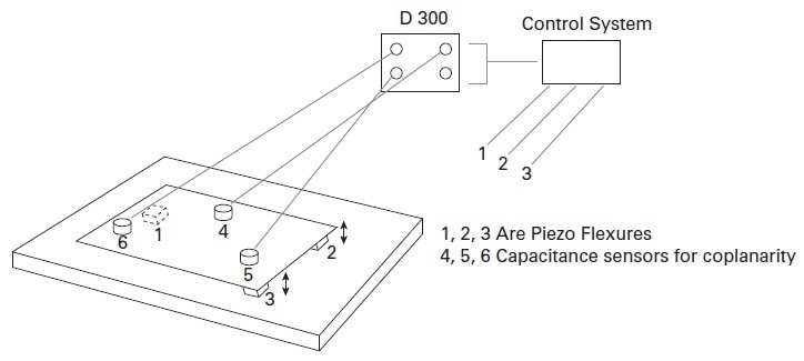
Three gap measuring probes mount to the upper plane (die bonding tool). A control system monitors coplanarity of the tool to the lower plane (die or substrate) and provides position control to the actuators.
Power Generation: Monitoring Gaps in the Wind Turbine Industry
As the demand for renewable energy continues to grow, wind turbine production has subsequently exhibited a steady increase in both power outputs and the number of installations. As consumers are becoming increasingly interested in the replacing their energy sources with wind, the maintenance of wind turbines has become an increasingly critical task to achieve.
More specifically, operators are interested in minimizing downtime and the potential catastrophic failure of these turbines as much as possible. To meet this goal, operators are interested in implementing sensor systems that are capable of predicting when maintenance will be required.
In fact, a leading manufacturer of wind turbine power generators recently approached MTI Instruments for the potential application of critical gap monitoring sensors for this exact purpose.
The main objective of the wind turbine manufacturer was to invest in sensors that can maintain peak efficiency by ensuring an optimal gap, withstanding harsh environments, last ten years or more and function in high magnetic fields. To achieve these specific requirements, long sensor cable lengths would be required for routing to the control panels.
MTI Instruments has recently introduced a three-component sensor system comprised of a passive capacitive displacement probe, a special interconnect cable designed to reduce magnetic loop pickup and a Digital Accumeasure capacitive amplifier.
The capacitance probe, which exhibits a thickness of less than 500 micrometers (µm), functions as one plate of a classic two-plate capacitive gap sensor of which the target, which is typically grounded, forms the second plate. This robust probe is composed of non-magnetic material and is sealed with a polyimide to avoid corrosion.
Additionally, the capacitance probe is specifically designed to comply with C4 ASTM environmental guidelines. The interconnect cables are custom designed to prevent magnetically induced currents that could cause noise or burn out a sensor cable.
Within this capacitance sensor system also exists a digital Accumeasure amplifier that functions by injecting a current into the probe and then measuring the impedance of the capacitive gap that is formed by the probe and target. The impedance is directly proportional to the gap, as demonstrated by the following formula:
Gap = (area of the probe x dielectric constant of air)/capacitance of the gap
Numerous gap monitoring sensor systems have been installedin wind turbine production facilities to provide a continuous and real-time measurement that is comparable to when tripwires or other non-dynamic solutions have been used. These sensor systems can also be used to monitor armature gaps, as well as measure small gaps in the energy, aviation and automotive industries.
Some of the specific benefits associated with the use of digital capacitance sensors for this purpose includes:
- Digital networking of gap sensors
- Superior range with high accuracy as a result of the correction to digital linearity
- A digital design that allows excellent thermal stability of the complete system
- Field programmable amplifier bandwidths

Gap monitoring sensors from MTI Instruments help wind turbine operators predict impending maintenance to avoid catastrophic failure.
Solar Technology: Monitor Ungrounded Targets
Today’s semiconductor and solar industries have increased the production demand for higher density chips that are of smaller critical dimensions. To this end, wafer fabricators have become increasingly interested in obtaining a greater dimensional control of their silicon products; a challenge that has now been achieved using non-contact capacitance sensors.
Some of the advantages associated with capacitance sensor systems involve their exceptional precision, accuracy and speed that allow for flatness, thickness, and other critical dimensions to be measured in a highly accurate manner.
The working principle of the MTI’s capacitance sensor systems involves the capacitance probe sensor acting as one plate of a classical two plate capacitive gap measurement scenario, in which the grounded target, which would be the silicon wafer for solar technology applications, forms the second plate. It is important to note that grounding can scratch or damage the fragile and expensive wafer.
Additionally, this process can also prohibit sensing scenarios during which the wafer must be moved to acquire all metrology measurements. To combat the challenges associated with grounding, parasitic capacitance coupling, a second sensor working 180 degrees out of phase or a grounded chuck to support the wafer can be implemented.
Despite these resolutions, they are limited in their effectiveness; this additional challenge has inspired MTI instruments to develop a push-pull probe that is specifically designed for ungrounded targets.
More specifically, the capacitance push-pull probe should be capable of measuring various scenarios that occur at the PV level. For example, to measure the thickness and warp of 156 mm2 photovoltaic (PV) wafers as they pass at the rate of one wafer per second at an accuracy of < 1 µm, MTI’s push-pull probe systems are used to measure ungrounded semiconductor wafers.
Based on conventional capacitance measurement principles, the design of the push-pull probe incorporates two capacitance sensors that are built into one probe body. Each sensor is drivenat the same AC voltage with a 180-degreephase shift between signals. This shift allows the current to travel across the target surface instead of through the target to ground, to ensure that any potential inaccuracies generated by the poorly grounded targets is completely eliminated.
MTI’s AS-562-PP amplifier sums up the individual output signals, producing a single 0 to 10 VDC output that is proportional to the probe-to-wafer gap at a sub-micron accuracy that is achieved at probe standoff distances up to two mm. For the solar industry, MTI’s capacitance sensor systems provide the following benefits:
- Push-pull technology:
- Passive
- Extremely stable over a wide temperature range
- Can be used on high bulk resistivity targets
- Do not require recalibration for changes in the target material
- The push-pull amplifier design cancels common mode electrical noise that may be induced in the target
- MTI’s PV-1000 digital controller:
- Accepts three capacitive thickness channels
- Provides digital correction for very high linearity
- Performs wafer sorting commands
- Computes pass/ fail metrology measurements
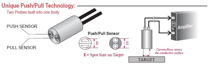
The Push-Pull probe is a unique version of MTI’s Accumeasure™ amplifier series. This special design provides accurate surface information for wafer bow and thickness.
Automotive Technology: Brake Rotor Thickness Variation
Today’s cars and trucks offer unprecedented fuel efficiencies and handling characteristics that is attributed to the lightweight of these vehicles. By light weighting all components of these vehicles, automotive technologies have reduced the stress and strain that is applied to the vehicle in an effort to improve the overall mileage and performance.
Similarly, the brake rotors of currently manufactured vehicles are also thinner and lighter as compared to those that were produced several years ago. Additionally, the implementation of cooling vents into brake rotors has further improved performance of these components. While useful, these changes to the brake system have also reduced the available braking surface, ultimately causing automotive engineers to consider alternative materials and designs.
Since these new designs, particularly those that involve incorporating cooling aspects to the brake system, improves the resiliency of these systems against rotor distortion and failure; the dynamic testing of these novel designs is imperative.
Herein, continuously obtaining data on disk run out, thickness variation, coning, warping and temperature during these testing procedures allows engineers to accurately determine the response rate of prototype units to real life conditions. To achieve these continuous measurements, MTI’s AccumeasureTM D Series is the company’s newest multi-channel brake rotor measurement system.
Within this system, the amplifier is equipped with advanced technology that changes a reliable capacitive electric field measurement into a highly accurate 24-bit digital reading. In doing so, any potential errors that arise as a result of analog filtering are eliminated, while also achieving an ideal linearization, range extension and summing of channels.
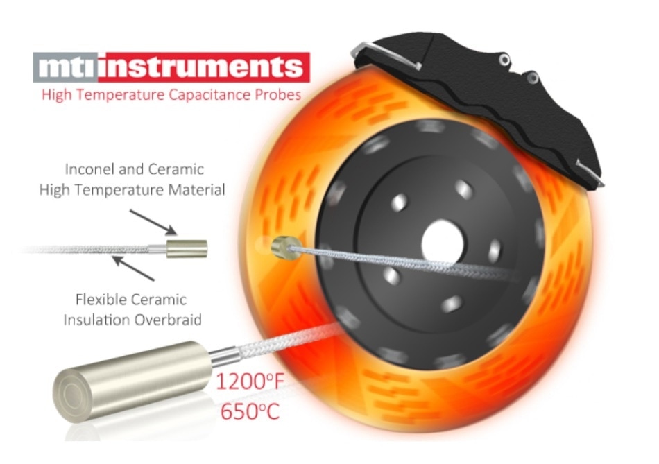
Single-ended capacitance probes or ‘push/pull’ capacitance sensors can be used for this specific application to monitor the distance between probe and rotor while spinning. When a push/pull sensor is used, the two sensing elements that are built into this single probe body eliminates the need to electrically ground the rotor. Comprised from Inconel and ceramic materials, the push/pull sensor probe is capable of withstanding temperatures as high as 1200 °F (650 °C).
Several major vehicle manufacturers have standardized on MTI’s Accumeasure high-temperature sensors and the AccumeasureTM D Series amplifier for their specified testing requirements. In addition to brake testing, these products are also being used to measure and monitor spindle and shaft run out, engine vibration, thermal expansion/contraction and suspension travel.
Some of the benefits associated with the use of MTI’s capacitance sensors for this specific industrial purpose include:
- The digital Accumeasure:
- Compact unit
- Runs off 24VDC
- Provides either four channels of single ended probes for a grounded target or two push pull probes for ungrounded rotors.
- Digital linearity correction allows for longer range probes to stay away from the hot rotor surface without losing accuracy.
- Digital Accumeasure features include:
- Linearity for accurate measurements
- Ethernet and USB ports
- Probe range extension for large stand-off distances.
MTI’s Accumeasure™ D Series amplifier provides up to four independent measurement channels in a rugged, compact amplifier package. Features include multiple unit synchronization, range extension, sub-micron resolution, and 0.01% error of full scale linearity. Push/pull probe design permits groundless, non-contact measurement of rotating targets.
Determining Oil System Contamination
The adverse effects associated with the contamination of water in oil include:
- Higher viscosity
- Reduced load-carrying ability
- Hydrolysis through the formation of acids, sludge and varnish
- Formation of foam and subsequent air entrainment
- Additive depletion
- Corrosion on metal surfaces
- Loss of lubrication film strength that ultimately increases wear to the system
- Cavitation
- Filter plugging
As the reliability of oil systems has dramatically decreased, the maintenance and repair activities associated with these systems have subsequently increased. To achieve corrective action, the use of in-line capacitance probes can offer both an automatic and continuous monitoring of water infiltration that enters lubrication systems.
Where oil typically exhibits a dielectric constant in the two to five range, water instead will often exhibit a dielectric constant of 80; therefore, even extremely small amounts of water can have a significant impact on the water state reading.
For this purpose, one capacitance probe is placedagainst a non-conductive section of piping that carries the oil supply to be monitored. A second reference probe is then placed against a sealed and non-conductive tube that contains a sample of the lubricating oil. Note that both tubes should be in thermal contact with each other. MTI offers flat flexible capacitance probes that can be easily bonded to the tubes.
Each capacitance probe bonded to the tubes must be able to measure the dielectric field that exists between the face of the probe and the grounded plate on the opposite side of tube. A monitoring CPU will initiate an alarm if the dielectric reading for the oil flow channel diverges from the sample reading.
By continuously measuring capacitance of the oil ratio to oil/water mixture through the tube, the overall moisture level of the oil system is minimized, thereby reducing potential corrosion effects, and ultimately improving the overall reliability of the system.
In conclusion, the specific benefits associated with the use of capacitance sensor systems for this application include:
- The digital Accumeasure:
- Equipped with a special calibration program built in to handle these types of dielectric calibrations
- Can communicate with an off the shelf USB alarm module to make a complete alarm system

MTI’s flexible, off-the-shelf flat probes easily bond to the tube with epoxy to mold to the shape of a plastic/glass oil tube and continuously monitor the capacitance of the oil or oil/water mixture passing through. The company’s D200 Digital Accumeasure serves as the monitoring sensor signal conditioner. Immune to thermal drift and easily calibrated to the sensitivity of water in oil, it is available with a digital limit alarm module.

This information has been sourced, reviewed and adapted from materials provided by MTI Instruments Inc.
For more information on this source, please visit MTI Instruments Inc.