Interference filters are frequently employed in transmissive configurations where the light passes through the filter to produce a specific effect (band-pass, long-pass, short-pass, among others).
These filters can also be used in reflective configurations where the filter reflects wanted light and rejects or absorbs the transmitted light.
Light is not usually absorbed by interference filters; all of the light is reflected or transmitted (as presented in Figure 1).
Some exceptions are known, especially in IR and UV, where the inherent features of the materials cause specific wavelengths to be absorbed. Scatter can also be observed at a small amount in most thin films.
Applications such as fluorescence and beam combining take advantage of this ability to reflect particular wavelengths while transmitting others.
Laser beams of different wavelengths are focused onto a single optical axis in beam combining. Dichroic mirrors are utilized in fluorescence to reflect excitation wavelengths and transmit fluorescence signals.
The total of the reflected and transmitted light is 100% when no absorption occurs.
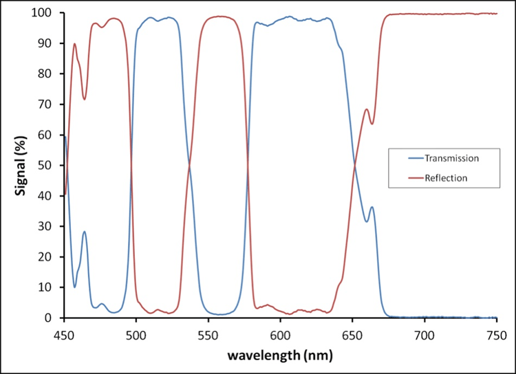
Figure 1. %T and %R of a filter at a 45° angle of incidence. These add up to 100% for most interference filters in the visible wavelength regime.
Baffle Filters - A reflective filter assembly is referred to as a ‘baffle filter’ by Omega. This is where multiple reflecting filters are positioned to produce the desired effect. Various configurations can be devised to focus the beam in a particular direction or to stabilize the optical axis (outlined in Figure 2).
Alternatively, the separate filters can be used as steering or folding mirrors in the customer’s optical system design.
One factor to consider is that the filter will function more successfully (steepest edges and highest transmission or reflection) at a single angle of incidence (AOI) in a collimated beam.
The splitting of s and p polarization usually occurs at higher AOIs, but some of this can be controlled when the filter is designed.
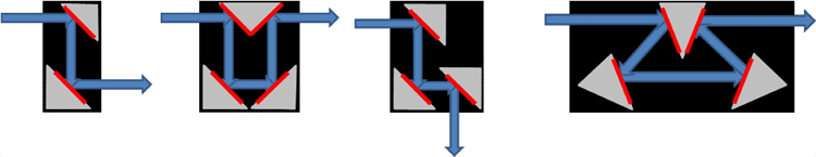
Figure 2. Some Baffle Filter designs at 45° and 22.5° AOI. These design concepts can be incorporated into nearly any optical system.
Applications and Performance
UV band-pass filters with visible light blocking - Most materials used for thin-film coating begin through the absorption of light in the UV (lower than approximately 350 nm).
The absorption makes it very difficult to produce a UV filter with high transmittance while blocking the entire visible spectrum simultaneously.
Induced transparency in metals (MDM design) is the traditional method used to achieve a particular level of transmission in the UV and strong visible blocking (shown in Figure 3). This filter category usually has a high blocking level, but a low transmission rate (less than 50%).
Higher transmission and steeper edges can be achieved with purely dielectric stacks (Figure 3) of materials that are UV-compatible. Unless very large stacks are used, the blocking range is limited.
Switching to a reflecting (baffle box) configuration with a 22.5° AOI provides a high %T in the band-pass and successful blocking in the visible caused by the use of absorbing epoxies in the assembly.
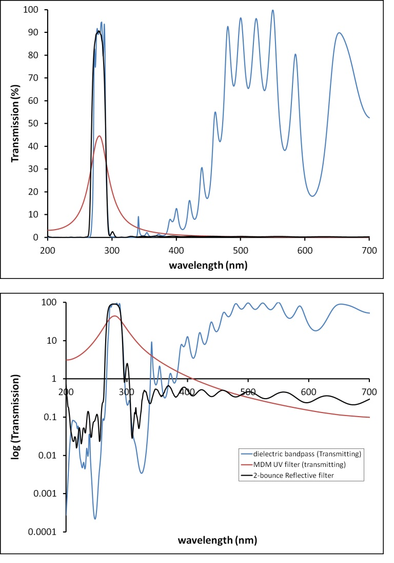
Figure 3. Comparison of MDM and transmissive UV filters with a 2- bounce reflective filter. Top: linear scale, Bottom: log scale to emphasize blocking. The reflective filter maintains narrow bandwidth, high throughput, and blocking over a wide wavelength range.
Narrow notch rejection filters - Due to the nature of thin-film interference filters, transmission notch filter designs are highly challenging, specifically when a high OD is required over a very limited wavelength.
Omega is skilled in producing very high transmitting narrow band-pass filters. They can create narrow notches when used in reflection.
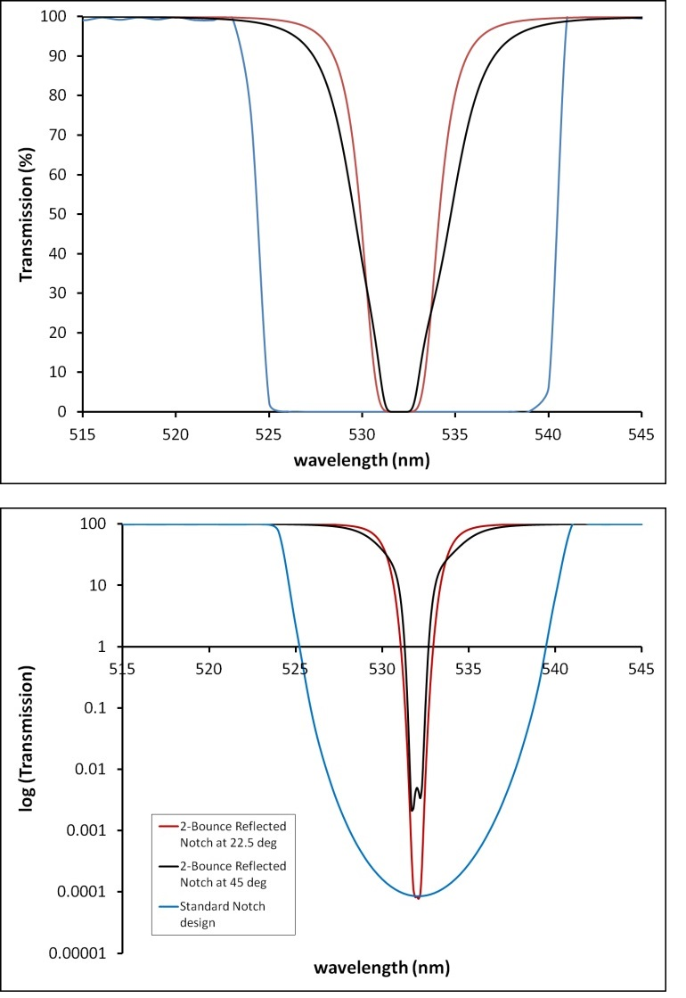
Figure 4. Top: A standard transmissive notch design with 2-bounce reflective notches designed at 2 AOIs. Bottom: The same data presented in log scale to show blocking (OD 6 in red and blue curves).
Utilizing this design technique, the width of the notch at 50% T can be reduced from approximately 16.5 nm (in the average transmission filter) to 6.2 nm wide at 45° and 4.3 wide at 22.5° AOI.
The notch is widened by increasing the AOI as a result of the splitting of the two polarization states (s and p) at an angle. This phenomenon can be seen in the bottom of Figure 4 as a double-dip in the black trace.
Omega helps its customers in ‘thinking inside the box’ with their continuing optical design projects.

This information has been sourced, reviewed and adapted from materials provided by Omega Optical, Inc.
For more information on this source, please visit Omega Optical, Inc.